
Guide


www.flexpoint.com Copyright
©
2015 Flexpoint Sensor Systems Page 5 of 15
Bend Sensor
v
+
V
OUT
R
M
+
-
v
+
R
3
R
2
R
1
Bend Sensor
v
+
V
OUT
R
M
+
-
v
+
R
5
R
6
R
4
v
-
R
5
+
-
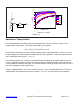
Figure 1.1 Figure 1.2
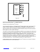
Adjustable Buffers:
Similar to the unity gain buffer, these interfaces isolate the output from the high source impedance of
the Bend Sensor
®
device. These alternatives allow adjustment of the output offset and gain.
In Figure 1.1, the ratio of resistors R
2
and R
1
sets the gain of the output. Offsets resulting from the non-
infinite Bend Sensor
®
resistance at zero deflection (or bias currents) can be trimmed out with the
potentiometer, R
3
. For best results, R
3
should be about one-twentieth of R
1
or R
2
. Adding an additional
pot at R
2
makes the gain easily adjustable. Broad range gain adjustment can be made by replacing R
2
and R
1
with a single pot.
The circuit in Figure 1.2 yields similar results to the previous one, but the offset trim is isolated from the
adjustable gain. With this separation, there is no constraint on values for R
6
. Typical values for R
5
and
R
6
are around 10 kΩ.