
Guide


www.flexpoint.com Copyright
©
2015 Flexpoint Sensor Systems Page 8 of 15
Bend Sensor
v
+
V
OUT
R
M
+
-
v
+
R
2
U1
R
1
R
3
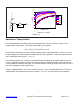
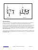
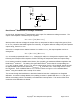
Figure 1.5
Bend Sensor
®
Variable Deflection Threshold Switch:
This simple circuit is ideal for applications that require on-off switching at a specified deflection, such as
touch sensitive membrane, cut-off, and limit switches. For a variation of this circuit that is designed to
control relay switching, see Figure 1.6 on the next page.
The Bend Sensor
®
device is arranged in a voltage divider with R
M
. An op-amp, U1, is used as a
comparator. The output of U1 is either high or low. The non-inverting input of the op-amp is driven by
the output of the divider, which is a voltage that increases with deflection. At zero deflection, the output
of the op-amp will be low. When the voltage at the non-inverting input of the op-amp exceeds the
voltage of the inverting input, the output of the op-amp will toggle high. The triggering voltage, and
therefore the deflection threshold, is set at the inverting input by the pot R
1
. The hysteresis resistor, R
2
,
acts as a “debouncer”, eliminating any multiple triggering of the output that might occur.
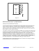
Suggested op-amps are LM358 and LM324. Comparators like LM393 and LM339 also work quite well.
The parallel combination of R
2
with R
3
is chosen to maximize the desired deflection sensitivity range. A
typical value for this combination is about 47 kΩ.
The threshold adjustment pot, R
1
, can be replaced by two fixed value resistors in a voltage divider
configuration.