
Guide


www.flexpoint.com Copyright
©
2015 Flexpoint Sensor Systems Page 9 of 15
Bend Sensor
v
+
R
M
+
-
v
+
R
2
U1
v
+
D1
Relay
Q1
R
3
R
1
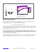
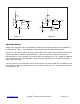
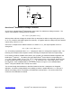
Figure 1.6
Bend Sensor
®
Variable Deflection Threshold Relay Switch:
This circuit is a derivative of the simple Bend Sensor
®
Variable Deflection Threshold Switch of Figure 1.5
on the previous page. It has use where the element to be switched requires higher current, like
automotive and industrial control relays.
The Bend Sensor
®
device is arranged in a voltage divider with R
M
. An op-amp, U1, is used as a
comparator. The output of U1 is either high or low. The non-inverting input of the op-amp sees the
output of the divider, which is a voltage that increases with deflection. At zero deflection, the output of
the op-amp will be low. When the voltage at the non-inverting input of the op-amp exceeds the voltage
of the inverting input, the output of the op-amp will toggle high. The triggering voltage, and therefore
the deflection threshold, is set at the inverting input by the pot R
1
. The transistor Q1 is chosen to match
the required current specification for the relay. Any medium power NPN transistor should suffice.
The threshold adjustment pot, R, can be replaced by two fixed value resistors in a voltage divider
configuration. The diode D1 is included to prevent flyback, which could harm the relay and the circuitry.