
Manual


7/9
VCA section
This is the output section. Each of the two signals is sent to a VCA,
and the outputs of the two VCA are summed together and sent to the output
jack.
Level:
The level control for the VCA. Fully clockwise is maximum
(±5V), and fully counter-clockwise is full attenuation.
CV Level:
Controls the attenuation of the external CV signal, used
here to vary the level of the output signal.
Volume control
This is the last stop for the signal on its way to the output jack,
the volume control. Turn clockwise for full volume, counter-clockwise for full
attenuation.
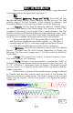
Rear Panel
Ext
In
Out VCO
CV
VCA1
CV
VCA2
CV
±12VAudio
On
Off
Freq
CV
Range
CV
fc1
CV
fc2
CV
12VAC
±12V0-5V
IMP Filters
Here are the I/O jacks (Input/Output). Only one “O” –
Out
, the
Output, the rest are “I” – the CV inputs mentioned above with the various
CV Level attenuators,
Ext In
, the external audio input, and the power
connections.
The CV inputs have their recommended input signal voltage range
specied above the jack – please do not exceed these values. The
Range
and
Freq
are specied for 0-5VDC, but also have zener protection diodes,
just in case the wrong signal is connected.
Power
The power section, with the ubiquitous power switch and power-
on indicator. The INM requires a 12VAC 250mA source. The power jack
accepts a 2.1mm x 3.5mm cylindrical-style power plug.
A binding post is provided for connection to equipment ground if
required. The barrel of the post accepts the standard 4mm banana plug,
and can be unscrewed to attach wires or other forms of connector.
g. 4