
Instruction Manual


4/7
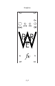
IMPORTANT
The LEDs are required for stable operation
at low levels of current draw.
This means they must be attached, even if you do not plan to panel-mount
them. Just put them on short leads (or even just solder them to the headers).
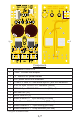
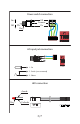
Power Connections
The power output connectors are standard 0.25” width male quick-connect
terminals, compatible with the standard Doepfer PSU harnesses and distribution
board terminals.
T+1 & T+2: +12V
T-1 & T-2: -12V
TG1 & TG2: System ground
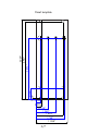
Compensation jumpers
Power supplies are infamous for mysteriously becoming unstable.
Their performance is dependent upon the type of load they are powering, and
no two systems are the same. As I have dealt with this sort of problem in the past,
there are provisions on the PCB to adjust the regulator output capacitors to tailor
output performance to your specic load characteristics.
The existing jumpers – JP1(V+) & JP2(V-) – bypass these provisions, and
are required for normal operation. The positions marked JP3 & JP4 are connected
in parallel with C4 and C8, respectively, and can be used to increase the
regulator output capacitance. Cut JP1 or JP2 as necessary to reduce the output
capacitance.