FlightLine OV-10 Bronco User Manual Wingspan: 1400mm Length: 1390mm Empty Weight: 3050G[w/o Battery] EN 1~10 中 11~20
1 2 2 3 3 3 4 4 5 6 6 7 8 9 9 10 10 Introduction Product basic information Package list PNP Assembly instructions Install main wing middle part Install two sides of the fuselage Install horizontal stabilizer Install main wing (Left and right side) Install propeller and spinner Install other accessories Pushrod instructions Install battery Center of Gravity PNP Parameter setting Control direction test Dual rates Flap-to-Elevator Mix Throttle correction Pre-installed component overview Servo direction Motor
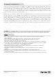
Products introduction Thank you for purchasing our FlightLine OV-10A Bronco. It features an upper single-wing, double-engine, twin-tailed beam layout with a 1390mm length and a wingspan of 1400mm. It is made of EPO material and is reinforced with carbon and fiberglass. The modular design, in addition to a small number of parts of the imitation decorative accessories, the body parts are fastened with screws. At the same time, the control board and the cable are used to optimize the line connection.
Product Basic information 1400mm(55.12 in.) Wingload:83.5g/dm² Wing Area: 44.5 dm² Motor: 3530-860KV O/R Motor ×2 Servo: 17g MG digital servo ×1 9g Hybrid digital servo ×9 ESC: 30A ×2 5A UBEC ×1 Propeller: 3-Bladed 9507 (Standard ×1, Reverse ×1) Weight: 3050g (w/o Battery) Other features Material:EPO & Plastic Aileron: Yes Split Flaps: Yes Elevator: Yes Rudder: Yes Landing gear: Electric Landing Gear Cabin door: No Scale LED lights Scale Pilot figure ×2 Li-Po Battery: 4S 3300-4000mAh ×2 1390mm(54.
PNP Assembly Instructions Install the main wing middle part 1.As the photo show, install the main wing middle part on the middle of fuselage. While placing, arrange and straighten all the cables, put them into the space shown by the arrow, make sure that no cables are pressed by the main wing, and then use screws to fix. Screw : PA 3×12mm 4pcs Install two sides of the fuselage Screw : PA 3×12mm 10pcs 2.
PNP Assembly Instructions Install Main wing (Left and Right Side) 4.Loosen the screws of wing control board which installed on the left/right main wing, and confirm that the servo wires are tightly connected. Then reinstall it. 5.Insert the ribbon wires into the left/right wing control board. 6.Fix the main wing with screws. Screw : PWM 3×6mm 4pcs Cabon tube : Φ 10×500mm 2pcs Install propeller and spinner Reverse Propeller Standard Propeller Screw : M3×6mm 2pcs Nut : M3×6mm 2pcs 7.
PNP Assembly Instructions Install other accessories 8 .As shown in the photo below, install various scale accessories such as antennas, machine guns, and hangers on the fuselage. Note: When installing, first try to install the correct accessories into the mounting holes to know the depth of the accessories installation. Then apply a small amount of glue to the part that needs to be inserted into the foam for installation.
PNP Assembly Instructions Pushrod instructions N ose ge a r st e e ring pushrod I e ngt h N ose ge a r st e e ring pushrod m ount ing hole Pushrod diameter : Ø1 . 2 mm 45mm ( 1- 13/16 ) Rudde r pushrod I e ngt h Rudde r pushrod m ount ing hole 1 2 3 4 158mm ( 6- 1/4 ″) Elevat or pushrod I e ngt h 58mm Pushrod diameter : Ø1 . 5 m m Aile ron pushrod I e ngt h ( 2- 9/16 ″) ( 2- 5/16 ) 1 2 3 4 2 3 Aile ron pushrod m ount ing hole Pushrod diameter : Ø1 .
PNP Assembly Instructions Center of Gravity Center Of Gravity Correct Center of Gravity (”CG”) is critical for enabling safe aircraft stability and responsive control. Please refer to the following CG diagram to adjust your aircraft’s Center of Gravity. - Depending on the capacity and weight of your choosen flight batteries, move the battery forward or backward to adjust the Center of Gravity.
P NP Parameter Setting Control Direction Test After installed the plane, before flying, we need a fully charged battery and connect to the ESC, then use radio to test and check that every control surface work properly. Ailero n S tic k Le ft S tic k Right Ru dder S tic k Le ft St ick R ight Elevator Stick down Stick up Flaps Flaps down 8 FlightLine OV-10 Bronco Item No.:FLW305 Version No.
P NP Parameter Setting Dual Rates According to our testing experience, use the following parameters to set Aileron/Elevator Rate. Program your preferred Exponential % in your radio transmitter. We recommend using High Rate for the first flight, and switching to Low Rate if you desire a lower sensitivity. On successive flights, adjust the Rates and Expo to suit your preference.
Pre-lnstalled Component Overview Servo Direction Left Side 6 8 4 1 2 3 If you need to purchase another brand’s servo, please refer to the following list to choose a suitable servo. Servo regulation No. 9g Digital-Hybrid 1 Pos. / Rev.