Catalog Introd uction······························ ..·················································································································1 Basic Information ........................................................................................................................................2 Package List······ ..........................................................................................................................................
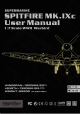
Introduction Thank you for purchasing the FlightlineRC 1600mm Spitfire Mk. lXc! FlightlineRC is a leading brand produced by Freewing Models in partnership with Motion RC aimed at bringing you a new, exciting series of propeller driven aircraft at the same level of quality and value you've come to expect from Freewing Model's EDF aircraft and other products. FlightLineRC inherits Freewing's goals of outstanding innovation, exquisite design, high quality, unbeatable value, and dependable performance.
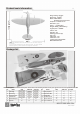
Product basic information EN Wing loading: 74g/dm2 Wing area: 46.5dm2 Motor: 5055-390KV brushless outrunner motor Propeller : 4-Blade 16x10 ESC: 80A (1pc) Servo: : 17g MGx6pcs Weight: 2850g (W/O battery) Flight speed: 125KMH .... M in E E 0 in M .... Aileron: Yes Elevator: Yes Steering pushrod: Yes Flap: Yes LED lights: Yes Cabin door: Yes Landing gear: Retractable. Material: EPO Foam 1600mm (63") Note!:The parameters stated here are derived from test results using our accessories.
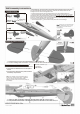
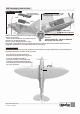
PNP Assembly Instructions Fuselage Assembly �--}· _...... step8 �;---- od __J Steering pushr !"! __ !!!_ !!!_!!! _!!!_!!!_!!!_O�..._ (710mm) """'� 1. Before assembly, remove the battery compartment and the fuselage pushrods in the plastic tube. Install the ball-head buckle on the pushrods. Then insert the rudder pushrod from tail fuselage section into the front fuselage plastic tube. 2. Insert the elevator pushrod from tail fuselage section to the front fuselage plastic tube. 3.
PNP Assembly Instructions EN 1. Insert one side of rudder pushrod A ,through plastic tube B, to the servo arm C. 2.Buckle the ball head buckle of rudder push rod to the rudder horn D. & Note: When installing the rudder pushrod, make sure the tail wheel is centered. Then install the rudder pushrod, and adjust the plastic clevis to center the rudder. 1. Use rudder pushrod to connect the tail gear steering arm and rudder horn. Aileron push rod Installation 1.Use servo tester or radio to center the servo.
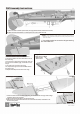
PNP Assembly Instructions EN Step(;) 5. Pull the main wing servo cables from the fuselage up into the battery compartment. 6. Insert the main wing plastic joiner pieces, A and B to the underside of the wing, as shown. Finally, use the four machine screws to attach the wing to the fuselage. �tic pieceA �-�"- .:, ' ' ,... -----F-------------.
PNP Assembly Instructions EN Scale parts Installation 1.Glue the Radiators A and B to the main wing surfaces, as shown. 2.Use 1xPWM4x8mm screw to attach the air intake. Screw -------- (PWM4x8 mm) Stepf) 4.Use clear canopy glue to attach the scale rearview mirror to the clear canopy. Do not use CA glue. CA glue may damage the clear canopy. Finally, insert the antenna into the top of the fuselage. Glue is not required. This part can be removed for transport. Rea�iew Micco, - �� Cannon barrels 3.
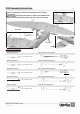
PNP Assembly Instructions N Battery Installation To remove the battery hatch, lift up on the tape. Place the battery into the front of the fuselage using the provided rubber matting or Velcro to secure it. Battery cabin size: L=260 W=76 H=45(mm) Before connecting the battery to the ESC, please The battery capacity and discharge rate we remove the propeller. advise is : Switch on the transmitter and ensure that the 6S 22.2V 3500mAh - 6S 22.2V 5000mAh ii throttle is in the lowest position.
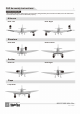
PNP Assembly Instructions N Control direction test After installed the plane, before flying, we need a fully charged battery and connect to the ESC, then use radio to test and check that every control surface work properly. Ailerons •- Stick Right Stick Left !!!!!!!! - •!!!!!!!! Elevators Stick Back Stick Forward Rudder Stick Left Sitck Right Flaps Flaps down !iPITFIRE MK.IXc lten No.
PNP Assembly Instructions N l•fftifiiiii According to our test results, the following rates proved to be a good starting point. Low rates are good for initial flights or for less experienced pilots. Adjust rates to suit your own style.
Accessories Description EN i!j "'" ,.· Servos Introductions · "'" ,. 0 ·� A servo or reversed servo is defined as follows: When the servo input signal changes j from 1000ųs to 2000ųs, if the servo arm, /__,// rotates clockwise, it's a positive servo. If �------ ------�/ it rotates counter clockwise, it's a reversed servo. Note: If you choose not to use the factory servo, the servo you choose may be larger.
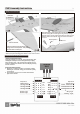
Accessories Description EN Power system installation /�- ------------------------------------------ ' A-Screw (KM4x8mm 4pcs) B-'Motor mount C-5O55-390KV out-runner motor D-Propeller hub E-Screw (HM2.5x1Omm 4pcs) C ' ,.---------------------------------------------------------,.
Accessories Description EN Main landing gear installation Assemble and disassemble the main landing gear according to the following photos. A-Main gear axle 8-Main wheel (0 85x26mm) C-Grub Screw (M4x4) 0-Main gear strut E-Grub Screw (M4x3) F -Main gear shock absorber active rod G-Nose gear shock absorber arm fixed part H-Screw (PM2x3 2pcs) I -Pin (03.5x12.6mm 1pcs) J -Pin (02x13.1mm 1pcs) K-Pin (03.5x7.3mm 1pcs) StepO Step@ L -C-Buckle (01.5mm) M-C-Buckle (01.5mm) N- C-Buckle (01.
Dongguan Freewing Electronic Technology Ltd HK Freewing Model International Limited Add.:FeiYi Building.face to Labor Bureau, Fumin Middle Road, Dalang Town, Dongguan City , Guangdong Province, China Web: http://www.sz-freewing.com Email:freewing@sz-freewing.com Fax:86-769-82033233 Tel: 86-769-82669669 *�"$"tJt�-=ff4!1��&0§J � � "t JI*�� 00 �ffi � �& 0 §J :1:-lR:l:Jl:: , *� *%m*M� I'� ��402-408% �Ji:li[Y:li Web: http://www.sz-freewing.com Email:freewing@sz-freewing.