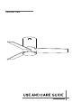
CEILING FAN
F6298110V Manual WARNING: SHUT POWER OFF AT FUSE OR CIRCUIT BREAKER
F6298 110V Manual WARNING: SHUT POWER OFF AT FUSE OR CIRCUIT BREAKER THANK YOU FOR YOUR PURCHASE Thank you for purchasing this quality product. To ensure correct function and safety, please read and save all instructions before using the product SAFETY TIP 1. To avoid possible electric shock, turn off the electricity at the main fuse box or circuit panel before you begin the fan installation or before servicing the fan or installing accessories. 2.
F6298110V Manual WARNING: SHUT POWER OFF AT FUSE OR CIRCUIT BREAKER Blade screws(10PCS) Mounting screws (2PCS) Plastic wire nut (3PCS) Balanced parts package(1PCS) washer (2PCS) 3 1 2H 2 4H 8H REMOTE CONTROL(1PCS) Mounting plate Fan-motor assembly Blade 3PCS Light plate Glass shade Pls check whether above accessories are completed or not?Yes,and install.
F6298110V WARNING: SHUT POWER OFF AT FUSE OR CIRCUIT BREAKER Outlet box washers 100% 70% 70% Mounting plate 100% Outnet box Mounting plate Washer Self tapping screw
F6298110V Manual WARNING: SHUT POWER OFF AT FUSE OR CIRCUIT BREAKER FROM POWER SOURCE AC 110- 120 VOLT 60Hz 3.5AMPS.
F6298110V Manual WARNING: SHUT POWER OFF AT FUSE OR CIRCUIT BREAKER Blade 3PCS Blade Screw 9PCS
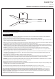
F6298110V Manual WARNING: SHUT POWER OFF AT FUSE OR CIRCUIT BREAKER Screw 3pcs Glass shade controls (SUMMER TIME) d A.warm weather-(Forward) A Downward airflow creates a cooling effect. This allows you to set your air conditioner on a higher setting without affecting your comfort. B.Cool weather-(Reverse) An upward airflow moves warm air off the ceiling.This allows Reverse you to set heating unit on a lower setting without affecting your comfort.
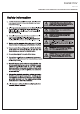
F6298110V Manual WARNING: SHUT POWER OFF AT FUSE OR CIRCUIT BREAKER Remote controller GENERAL INFORMATION This remote controller is desianed to separatelv control vour ceilina fan speed and light on and off. There are four buttons(HI,MED, LoW,OFF) to control the speed of the fan and off. The light button will control the light on and off. The red indicator on the transmitter will light when one of the five buttons is pressed. INSTRUCTION OF INSTALLATIONAND OPERATION 1.
F6298110V Manual WARNING: SHUT POWER OFF AT FUSE OR CIRCUIT BREAKER If other fans or supply wires are different color, have this unit installed by qualified licensed electrician. e.Push all connected wires up into junction box. f. Lay the brown antenna wire on top of the receiver, and put the receiver into the mounting bracket. g.Reinstall the canopy on the mounting bracket. h.Restore power. 3.OPERATINGTRANSMITTER: A. lnstall1.5 volt battery(not included).
F6298110V Manual WARNING: SHUT POWER OFF AT FUSE OR CIRCUIT BREAKER size of product 10" 7" 1" 82 48" " Ø48
F6298 WARNING: SHUT POWER OFF AT FUSE OR CIRCUIT BREAKER TROUBLESHOOTING GUIDE Table of Contents 1. 2. 3. 4. Fan / Remote is not working Fan is noisy Fan Wobbles Light is not working Please refer to the instruction sheet for detailed directions and descriptions of installation steps and requirements. 1. FAN / REMOTE IS NOT WORKING Ensure the remote is within the 20 foot range of the receiver To reset the remote control: 1) Turn off power to fan using the wall switch or circuit breaker.
F6298110V Manual WARNING: SHUT POWER OFF AT FUSE OR CIRCUIT BREAKER 3. THE FAN WOBBLES Verify all blades and blade bracket screws are secure (most fan wobble problems are caused by loose parts). Once fan is properly installed, run the ceiling fan for 10 minutes to let the fan self-adjust. If wobble occurs a er running the fan for 10 minutes, verify blade level using the following process: a) select a point on the ceiling above the p of one of the blades.
F6298110V Manual WARNING: SHUT POWER OFF AT FUSE OR CIRCUIT BREAKER AFTER INSTALLATION WOBBLE” The fan blades have been adjusted in the factory to minimize any wobble NOTE:CEILING FANS TEND TO MOVE DURING OPERATION DUE TO THE FACT THAT THEY ARE MOUNTED ON A RUBBER CROMMET. IF THE FAN WAS MOUNTED RIGIDLY TO THE CEILING, IT WOULD CAUSE EXCESS VIBRATION.