
Owner's manual

4 (FW1086)
95 North Oak St. • Kendallville, IN 46755 • 1-800-345-9422
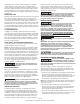
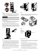
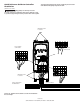
There should be at least 4 inches of
clearance on each side and below the unit to allow room for
air flow.
IL0735
4”
Min
4”
Min
4”
Min
Motor Pump
Inlet
Pressure Relief
Valve
Tank
Pressure
Sensor
Leads
Pressure Tank to
Pressure Sensor
Mounting
Clearance
Outlet
Power to
Motor
Power Supply from Circuit Breaker
4” Min
6 Ft.
or Less
Figure 3a - Mounting Clearance - Booster Pumps
IL0784
4”
Min
4”
Min
4”
Min
Motor
Pump
Inlet
Pressure Relief
Valve
Tank
Pressure
Sensor
Leads
Pressure Tank to
Pressure Sensor
Outlet
Power to Motor
Power Supply
from Circuit
Breaker
4” Min
6 Ft.
or Less
Figure 3a - Mounting Clearance - Centrifiugal Pumps
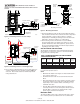
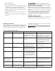
4. Do not expose a Artesian Drive to rain or water spray. For
outdoor installations, place the drive inside a NEMA 3R
enclosure. Note: Please reference maxim temperature
ratings listed above.
Correct
Power to
Motor
Pressure
Sensor
Leads
Mounting Orientation
Power
Supply
from Circuit
Breaker
Incorrect
Power
to Motor
Pressure
Sensor
Leads
Power
Supply
from
Circuit
Breaker
IL0734
Figure 4 - Mounting Orientation
5. The Artesian Drive should only be mounted with the wiring
end oriented downward. The controller should not be placed
in direct sunlight or other locations subject to extreme
temperatures or humidity (mounting location should not be
subjected to freezing conditions or condensation).
6. The mounting location should have access to 230 VAC
electrical supply and to the pump motor wiring. To avoid
possible interference with other appliances, please refer to
the enclosed Installation Guide and observe all precautions
regarding power cable routing.
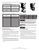
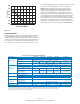
CIRCUIT BREAKER AND WIRE SIZING
The minimum circuit breaker size and maximum allowable
wire lengths for connection of motor to the Artesian Drive
are given in the following table:
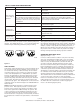
TABLE 1: MINIMUM BREAKER SIZE AND MAXIMUM
CABLE LENGTH (IN FEET)
Drive
Model
Recommended
Input Cable
Recommended
Motor Cable
Maximum
Cable
Length to
Motor (Ft.)
Recommended
Breaker
Maximum
Continuous
Current
AD052045 12 16 325 20 5.2
AD070059 12 16 325 25 7.0
AD096074 10 14 325 30 9.6
AD096096 10 14 325 30 9.6
AD150145 8 12 325 30 15.0
A 10-foot section of cable is provided with the Artesian Drive
to connect the pressure sensor.
NOTE:
• Maximum allowable wire lengths are measured between
the controller and motor.
• Aluminum wires should not be used with the Artesian
Drive.
• Wire sizing between the service entrance and the control-
ler must be sufficient to provide the required maximum
input amps to the controller while conforming to local
standards and codes.
• Artesian Drive minimum breaker amps may appear to
exceed specifications for the three-phase motor because
Artesian Drive controllers are supplied from a single-
phase service rather than three-phase.
Pressure Tank
The Artesian Drive needs only a small pressure tank to main-
tain constant pressure (see table below for recommended