
Owner's manual

5 (FW1086)
95 North Oak St. • Kendallville, IN 46755 • 1-800-345-9422
tank size). The Artesian Drive can also use a bigger tank with
a much larger capacity if available.
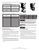
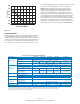
TABLE 2: MINIMUM PRESSURE TANK
Rated Pump Flow Pressure Tank Size (Total
Volume)
Pump Capacity less than 12
GPM
4 Gallon (AT15)
Pump Capacity greater than
12 but less than 25 GPM
8 Gallon (AT25)
Pump Capacity greater than
25 GPM
14 Gallon (AT44)
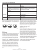
The pressure tank pre-charge setting should be 70% of the
system pressure sensor setting as indicated in the following
table.
TABLE 3: PRESSURE TANK AIR PRECHARGE (PSI)
System Pressure (at Pressure
Sensor)
Pressure Tank Precharge
Setting (± 2 PSI)
30 21
35 25
40 28
45 32
50 35
55 39
60 42
65 46
70 49
75 53
80* 56
*NOTE: High pressure applications above 80 PSI should
be addressed through the Tech Support group at Flint &
Walling (1-800-345-9422).
Installation Procedure
1. Disconnect electrical power at the main breaker.
2. Drain the system of water (if applicable).
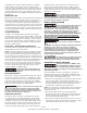
3. Install the pressure sensor (threaded connection down) at
the pressure tank tee downstream of the pressure tank (the
pressure tank should be between the pressure sensor and
the pump). The pressure sensor has a 1/4-18 National Pipe
Thread (NPT) connection.
NOTE: The pressure sensor should not be installed in an
inverted orientation (threaded connection up). Make sure the
pressure sensor and tank are not located more than 3 feet off
the main piping.
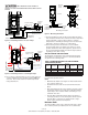
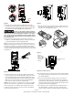
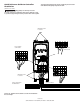
4. The unit should be mounted on a sturdy supporting
structure such as a wall or supporting post. Please take into
account the weight of the unit (refer to the Specifications
section under the appropriate model). Install the unit to the
wall using six mounting screws (not included) as shown in
Figure 5.
H
W1
2-3/8”
W2
IL0746
Figure 5
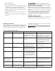
TABLE 4: DIMENSIONS
Drive Model H W1 W2
AD052045 7-1/2” 2-3/16” 2-3/16”
AD070058 7-1/2” 2-3/16” 2-3/16”
AD096096 9-1/2” 2-3/4” 2-3/4”
AD150145 12-13/32” 3-13/32” 3-13/32”
Wiring Connections
!
Serious or fatal electrical shock may result
from failure to connect the motor, the Artesian Drive, metal
plumbing and all other metal near the motor, or cable to the
power supply ground terminal, using wire no smaller than
motor cable wires. To reduce risk of electrical shock, disconnect
power before working on or around the water system.
!
To avoid a fire hazard and maintain validity
of the UL listing, torque the power terminal screws to 12 lb.-in.
(1.4 N-m).
!
Do not use motor or system in swimming
areas.
BEFORE BEGINNING WIRING
1. Verify that the power has been shut off at the main breaker.
2. Verify that the dedicated branch circuit for the Artesian
Drive is equipped with a properly-sized circuit breaker. Refer
to Table 2 (Page 8) for minimum breaker size.
3. Insert the provided strain relief into the mounting holes on
the bottom of the enclosure. (Strain relief fittings are not
supplied for the motor supply cable and power supply leads
on AD150145).
4. Remove the Artesian Drive cover. Line up the alignment
notches and slip the memory stick into the slot on the front
of the controller. Note: Do not force the stick into place; it
should slip into the slot and protrude about 3/4” from the
face of the controller with the cover off when fully seated.