
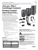
Owner's manual

7 (FW1086)
95 North Oak St. • Kendallville, IN 46755 • 1-800-345-9422
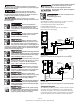
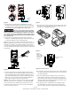
the following procedure:
a. Remove the rubber end-cap.
b. Using a 7/32” Allen wrench (provided), turn the adjusting
screw clockwise to increase pressure and counter-
clockwise to decrease pressure. The adjustment range is
between 30 and 80 psi (1/4 turn = approximately 3 psi).
c. Replace the rubber end cap.
d. Reset the pressure tank pre-charge to the appropriate
pressure.
e. Cover the pressure sensor terminals with the rubber boot
provided.
When increasing the pressure, do not
exceed the mechanical stop on the pressure sensor or 80 psi.
The pressure sensor may be damaged.
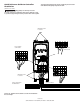
NOTE: Ensure that the system is properly grounded all the
way to the service entrance panel. Improper grounding may
result in the loss of voltage surge protection and interference
filtering.
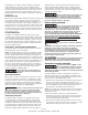
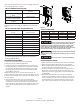
SPECIAL INSTRUCTIONS FOR OUTDOOR INSTALLATION
To install the Artesian Drive in an outdoor installation,
the drive must be placed inside NEMA 3R enclosure (Not
Included).
Start-Up and Operation
Apply power to the controller. As long as the display is lit up
the system has power. When the display shows . or
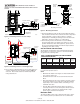
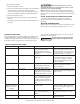
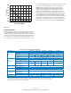
TABLE 5: DIAGNOSTIC FAULT CODES
DISPLAY CODE FAULT POSSIBLE CAUSE CORRECTIVE ACTION
Motor Underload Air-locked pump. Overpumped
or dry well. Worn pump.
Damaged shaft or coupling.
Pump deadhead. Blocked pump
or screen.
Wait for well to recover and auto-
matic restart timer to time out. If
the problem does not correct, check
motor and pump. See description of
“Intelligent Reset” on Page 18.
Undervoltage Low line voltage. Misconnected
input leads.
Check for loose connections. Check
line voltage. Report low voltage
to the power company. Unit will
start automatically when the proper
power is supplied.
. Locked Pump Motor/pump misaligned.
Abrasive/Sand-bound pump.
Dragging pump or motor.
Unit will attempt to free a locked
pump. If unsuccessful, check the
motor and pump.
. Short Circuit When fault is indicated imme-
diately after power-up, short
circuit due to loose connection,
defective cable, splice or motor.
Check motor wiring. Turn power off
till display darkens then apply power
again to reset.
. Over Current When fault is indicated while
motor is running, over current
due to loose debris trapped
in pump, or water demand is
exceeding pump & motor’s capa-
bility.
Check pump.
.
(Number other than
0.0 & motor is not
running)
Open Circuit Loose connection. Defective
motor or cable.
With power off, check motor, motor
wiring and splices. Make certain all
connections are tight. Apply power
again to reset.
. . Overheated Controller High ambient temperature.
Direct sunlight. Obstruction of
air-flow.
This fault automatically resets when
the temperature returns to a safe
level.
. Controller Stopped Loose jumper wire Re-insert jumper wire into control
terminals B2 & B4.
DIAGNOSTIC FAULT CODES
Should an application or system problem occur, built-in diag-
nostics will protect the system. The display will change to
indicate the nature of the fault. In some cases, the system will
shut itself off until corrective action has been taken. Fault
codes and the recommended corrective action for each are
listed in the following chart.
!
Do not attempt to carry out internal
repairs. Return a faulty drive to the
supplier for repair.