
Owner's manual

8 (FW1086)
95 North Oak St. • Kendallville, IN 46755 • 1-800-345-9422
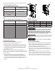
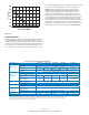
TABLE 6 SYSTEM TROUBLESHOOTING GUIDE
Symptom Possible Cause Corrective Action
Water flow rate
is not as high as
expected.
Motor/Pump is running backwards. Reverse connection of motor cable wires at connection
point U & V.
Pump capacity cannot supply the demand. Use pump with higher flow rating (if head requirement is
still satisfied).
Temperature in the controller is too high. If
the controller’s heat exchanger becomes too
hot, the controller will reduce the switching
frequency to the motor to lower the power
consumption.
Make sure there is at least 4 inches of room around the
controller for movement of air. Avoid direct sunlight.
Reduce ambient temperature below 104°F (40°C). Increase
input voltage if below 230 VAC.
Disconnected or broken wire feeding motor. Check motor, motor wiring and splices. Make certain all
connections are tight.
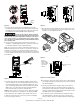
Excessive pres-
sure fluctuations.
Waterlogged tank. Check tank for bladder damage. Replace if necessary.
Reset the tank pre-charge pressure (should be 70% of pres-
sure sensor setting).
Pressure tank is too small for flow rating of
the pump.
Use larger tank (refer to Table 3 on Page 4 for minimum
Pressure Tank size).
Motor runs con-
tinuously with
no flow demand.
Leak in the household or outdoor plumbing. Check for leaky faucets, valves and/or pipe fittings and
repair.
Leak in the pitless adapter. Re-seat the pitless adapter. Replace seal as needed.
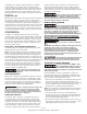
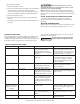
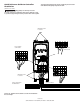
flashes PLC as shown, the system is active, but the pump is not
running. The display will show . as shown (where the
numbers may be fluctuating) when the pump is running.
IL0748
Figure 11
LEAKY SYSTEMS
Leaky water systems might keep the controller running due to
the accurate pressure sensing capability of the pressure sen-
sor. Continuous running or starts and stops do not hurt the
controller, pump or motor. However, to reduce the on-time
of the controller/pump/motor, a “Bump-Mode” procedure
has been programmed into the drive. During very low flow
(or leaky) conditions this feature periodically increases the
speed of the pump several PSI above the set point and shuts
off the pump. This adds some time to bleed off before the
system starts up again. This “Bump-Mode” can be turned off
if desired. Please call Technical Support at 1-800-345-9422 for
further details.
NOTE: Artesian Drive maintains a constant pressure at the
pressure sensor. Although the pressure is constant at the
pressure sensor, pressure drops may be noticeable in other
areas of the system when additional taps are opened. This
is due to restrictions in the plumbing and will be more pro-
nounced the farther the taps are from the pressure sensor.
This would be true of any system, and if observed, should not
be interpreted as a failure in the performance of the Artesian
Drive.
Although the pressure sensor can be adjusted up to 80 PSI,
the maximum obtainable pressure in the system is dependent
upon the full load capability of the pump at a given flow. For
example, a pump is only capable of producing a pressure of
60 PSI at the flow demand. Increasing the pressure setting of
the pressure sensor to 75PSI would only result in the pump
running at full speed and producing a pressure of 60 PSI.
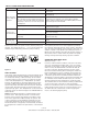
UNDERLOAD INTELLIGENT RESET
(Display showing )
If a motor Underload fault condition occurs, the most likely
cause is an overpumped well (dry well) or loss of incoming
feed water to the pump. In a dry well situation to allow the
well to recover, the Artesian Drive controller will wait 30
seconds to 5 minutes, determined by the amount of time
the motor had been running before sensing the underload,
before restarting the motor. For example, the first time the
fault occurs and the pump has been running 6 minutes, the
controller stops the motor and will wait 30 seconds before
attempting to restart the pump. If the system would then run
for 2 minutes and an underload fault recurs, the controller
will wait 3 minutes before attempting to restart the pump.
This schedule allows for the minimum off-time possible based
on the recovery time of the well or water feed supply.
If there is an obstruction (such as a closed valve) between the
pump and the pressure sensor, the controller will also sense
an underload is this “dead head” condition stopping the
motor to avoid damaging the pump.