
Instructions User guide

1
FLINT & WALLING, INC. • 95 North Oak St. • Kendallville, IN 46755 • www.flintandwalling.com
022354
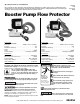
Booster Pump Flow Protector
Operating Instructions & Parts Manual
Please read and save these instructions. Read carefully before attempting to assemble, install, operate or maintain the product
described. Protect yourself and others by observing all safety information. Failure to comply with instructions could result in per-
sonal injury and/or property damage! Retain instructions for future reference.
FW1023
1106
Supersedes
NEW
General Safety Information
Carefully read and follow all safety instructions in this
manual and on pump. Keep safety labels in good condition.
Replace missing or damaged safety labels.
This is a SAFETY ALERT SYMBOL. When you
see this symbol on the pump or in the manual,
look for one of the following signal words and
be alert to the potential for personal injury or
property damage.
Warns of hazards that WILL cause serious
personal injury, death or major property damage if ignored.
!
Warns of hazards that CAN cause serious
personal injury or death, if ignored.
Warns of hazards that MAY cause minor
personal injury, product or property damage if ignored.
IMPORTANT: Indicates factors concerned with operation,
installation, assembly or maintenance which could result in
damage to the machine or equipment if ignored.
NOTE: Indicates special instructions which are important but
are not related to hazards.
Verify motor is wired for correct
voltage. See motor wiring diagram provided
by the pump or motor manufacturer.
Ground motor before connecting to
power supply.
Meet United States National Electrical
Code and local codes for all wiring.
Do not handle a pump, pump motor
or control unit with wet hands or when
standing on a wet or damp surface or in
water.
Hazardous
voltage. Can
shock, burn or
cause death.
Ground pump
before connecting
to power supply.
!
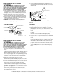
Follow wiring instructions in this manual when
connecting to power lines.
!
Always disconnect power source before
performing any work on or near the motor or its connected
load.
Control Box
115V SPECIFICATIONS
Enclosure . . . . . . . . . . . . . . . . . . . . NEMA 1 Indoor Use Only
Voltage . . . . . . . . . . . . . . . . . . . . . . . . . . . . . . . . . . . . . . . 115
Maximum HP Rating . . . . . . . . . . . . . . . . . . . . . . . . . . . . .3/4
Phase . . . . . . . . . . . . . . . . . . . . . . . . . . . . . . . . . . . . . . . . . . . 1
Hertz . . . . . . . . . . . . . . . . . . . . . . . . . . . . . . . . . . . . . . . .50/60
Contact Rating . . . . . . . . . . . . . . . . . . . 15 Amps @ 115/Volts
Flow Sensor
Contact Rating . . . . . . . . . . . . . . . . . . . . . . . . . . . .Max 20VA
Min. Flow for Contat Closure . . . . . . . . . . . . . . . . . . .1 GPM
Pressure Rating . . . . . . . . . . . . . . . . . . . . . . . . Max. 150 PSIG
Temperature Rating . . . . . . . . . . . . . . . . . . . . . . 32 to 140˚ F
Inlet and Outlet . . . . . . . . . . . . . . . . . . . . . . . . . . 1” Slip PVC
Control Box
230V SPECIFICATIONS
Enclosure . . . . . . . . . . . . . . . . . . . . NEMA 1 Indoor Use Only
Voltage . . . . . . . . . . . . . . . . . . . . . . . . . . . . . . . . . . . . . . . 230
Maximum HP Rating . . . . . . . . . . . . . . . . . . . . . . . . . . . . . . 2
Phase . . . . . . . . . . . . . . . . . . . . . . . . . . . . . . . . . . . . . . . . . . . 1
Hertz . . . . . . . . . . . . . . . . . . . . . . . . . . . . . . . . . . . . . . . .50/60
Contact Rating . . . . . . . . . . . . . . . . . . . 20 Amps @ 230/Volts
Flow Sensor
Contact Rating . . . . . . . . . . . . . . . . . . . . . . . . . . . .Max 20VA
Min. Flow for Contat Closure . . . . . . . . . . . . . . . . . . .1 GPM
Pressure Rating . . . . . . . . . . . . . . . . . . . . . . . . Max. 150 PSIG
Temperature Rating . . . . . . . . . . . . . . . . . . . . . . 32 to 140˚ F
Inlet and Outlet . . . . . . . . . . . . . . . . . . . . . . . . . . 1” Slip PVC