
Instructions User guide

2
FLINT & WALLING, INC. • 95 North Oak St. • Kendallville, IN 46755 • www.flintandwalling.com
Do not use to pump flammable or explosive
fluids such as gasoline, fuel oil, kerosene,
etc. Do not use in flammable and/or explosive
atmospheres.
Hazardous pressure! Install pressure relief
valve in discharge pipe. Release all pressure on
system before working on any component.
1. Make workshop child proof - use padlocks, master
switches; remove starter keys.
2. Wear safety glasses when working with pumps.
3. Wear a face shield and proper apparel when pumping
hazardous chemicals.
4. Keep work area clean, uncluttered and properly lighted;
replace all unused tools and equipment.
5. Provide guarding around moving parts.
6. Keep visitors at a safe distance from the work area.
7. Periodically inspect pump and system components.
8. Protect electrical cord. Replace or repair damaged or
worn cords immediately.
9. Do not insert finger or any object into pump or motor
openings.
!
This product contains chemicals known
to the State of California to cause cancer and birth defects or
other reproductive harm.
!
Risk of Electric Shock. This controller has
not been investigated for use in swimming pool areas.
LOCATION
!
In any installation where property
damage and/or personal injury might result from an
inoperative or leaking pump due to power outages,
discharge line blockage, or any other reason, a backup
system(s) should be used.
!
Install a pressure relief valve on any
installation where pump pressure can exceed the plumbing’s
maximum working pressure or on systems where the
discharge line can be shut off or obstructed. Extreme over
pressure can result in personal injury or property damage.
This unit is not waterproof and is not
intended to be used in showers, saunas or other potentially
wet locations. For outdoor installations, control unit must
be protected from the elements by a cover. This unit is not
weatherproof nor is it able to be submersed in water or any
other liquid.
DESCRIPTION
For pressure boosting systems, the electronic flow sensor-
control unit monitors the flow of water and automatically
shuts off the motor when the flow drops below 1.0 GPM.
Once the flow has increased above 1.0 GPM, the unit will
automatically turn the motor back on to boost the system
pressure. The device protects against dry run or dead head
conditions that are caused by a low yield water supply or
an obstructed water discharge. Note: This electronic flow
protection system is designed to be used with a positive
supply of water feeding the pump.
NOTE: The unit will not function if the pump is used in a
suction lift application.
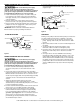
IL0631
F&W
115 VOLT
INLET
OUTLET
CONNECTORS
BOOSTER
CONTROLLER #2
FLOW
SENSOR
ELECTRONIC CONTROL
115 VOLT INSTALLATION
Figure 1
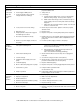
F&W
PAT.
PEND
230 VOLT
INLET
OUTLET
CONNECTORS
FLOW
SENSOR
ELECTRONIC CONTROL
FUSE DISCONNECT OR
BREAKER BOX
230 VOLT INSTALLATION
IL0629
Figure 2
INSTALLATION
1. Electronic flow protector box should be located within six
feet of the pump motor and power supply and should be
mounted to a solid surface.
Note: Follow all recommended installation procedure for
pump as provided by pump manufacture.
2. Plumb flow sensor on into the inlet side of the pump,
making sure that your water supply line is feeding the
inlet port of the flows sensor and the outlet port of the
flow sensor is plumbed to the inlet port of the pump (See
Figures 1 & 2). Use standard medium bodied PVC solvent
cement to attach piping to flow switch.
Care should be taken to use the minimum
recommended amount of PVC cement to insure that no
excess cement enters into the sensor of the unit and causes a
malfunction which can void the warranty.
If dirt, sand, debris or other particulate is
present in the supply water, install a strainer or filter on the
inlet side of the flow sensor to insure proper operation of
sensor and pump.
3. Plug the two red wires from the electronic flow protector
box into the two red wires on the flow sensor.