
Installation Guide Manual

Centrifugal
Constant Pressure
Installation Guide
Please read and save these instructions. Read carefully before attempting to assemble, install, operate or maintain the product described. Protect yourself and others by observing all
safety information. Failure to comply with instructions could result in personal injury and/or property damage! Retain instructions for future reference.
FW1101
0711
Supersedes
1008
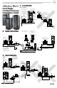
1. LOCATION
Indoor Use Only
2. WIRE ROUTING
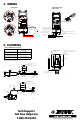
3. GROUNDING
IL0737
4”
Min.
4”
Min.
4”
Min.
4”
Min.
IL0738
IL0739
MOTOR
IL0740
IL0741
IL0742
IL0743
IL0744
Mount the Artesian Drive
unit as close as possible
to the service entrance
panel.
Use a dedicated branch circuit for the Artesian
Drive. Wire directly from the service entrance
panel.
Use the holes and
guides provided
Allow a 4”
clearance around
the Artesian
Drive box for
cooling
Mount unit to a sturdy
supporting structure (wall or
post)
DO NOT drill
holes in the
Artesian Drive
box
DO NOT wire to a sub panel
located in a home.
It is preferable to wire directly to
the service entrance panel.
When possible, DO NOT run
Artesian Drive input power or
motor wires in parallel with
house wiring.
Avoid runing out-building wires
in parallel with motor wires.
Keep input power and motor
wiring separated by at least 8”.
Input power Motor
DO NOT run input power and
motor wires together.
Keep separated by at least 8”
If it is necessary to run wiring in paralell, keep
Artesian Drive input power and motor wires at least
8” from other house wiring.
Cross over other branch
circuits and house wiring
at 90º
Insure that a
proper utility
ground rod is
present and
connected.
A dedicated ouput ground
wire from the Artesian
Drive must be connected
to the motor (motor wires
and ground wires must be
bundled together).
An input power ground wire from the supply panel
must be connected to the Artesian Drive.
Use the service
entrance panel
ground ONLY
DO NOT run
ground wire separate.
Motor ground wire MUST be
bundled with motor wires.
Avoid multiple ground paths
Service Entrance
Panel
Service Entrance
Panel
Service Entrance
Panel
Service Entrance
Panel
Service Entrance
Panel
Service Entrance
Panel
Service
Entrance Panel
IN HOME
Sub Panel
GND
GND
GND
Motor
GND
GND
Motor Pump
GND
GND
GND
GND
Service
Entrance Panel
Branch 3
Branch 2
Branch 1
8” Min.
8” Min.
Telephone
Motor
8” Min.
Satellite /
Antenna
Wire
GND
GND
8” Min.
OK
8” Min.
90º
GND GND
GND
8” Min.
GND.
GND.
Motor
Pump
GND.
GND.
Motor Pump
GND.
GND.
GND.
GND.
GND.
Motor
Pump
022688
Insure that a proper utility ground
rod is present and connected.
IL0783
Motor
Power to
Motor
Power Supply from Circuit
Breaker
Inlet
Outlet
Inlet
Outlet
Inlet
Outlet
Inlet
Outlet
Inlet
Outlet