Process Indicator Type DAS 72.1 Mark III MANUAL Firmware Version 72.181.v.4.28 or higher Hardware Version 72.101.5.v.3.0x Document No G128 Rev6 GB www.flintec.com Manual DAS 72.
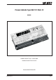
A GENERAL A.1 INTRODUCTION AND SPECIFICATION The model DAS 72.1 Mark III is a high precision, high speed digital amplifier for weighing and force measurements with strain gauge (SG) sensors. The device can be controlled either by the front keys or via RS 485 port. 3 Logic inputs and outputs make complex control functions easy. The 3 logic outputs can be controlled external too. With the available as standard analogue output 4…20 mA the DAS 72.1 fulfills industrial requirements.
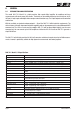
A.2 KEY FUNCTIONS Tare Key Puts unit into ‘Net’ mode. When inside ‘Set-up’ Menu this key moves the menu back one step. Also moves ‘Digit Selected’ to the right inside sub menus. Zero Key Sets new zero (if enabled). Reverts to calibrated zero if the button is held down for more than 3 seconds. Switches unit back to ‘Gross’ mode if a tare has been set. Acts as the ‘Enter’ key in the ‘Set-up’ Mode. Down key Recessed Enable Switch (Enables changes to be made to important parameters.
B KEYBOARD SET UP A GENERAL 2 A.1 INTRODUCTION AND SPECIFICATION 2 A.2 KEY FUNCTIONS 3 KEYBOARD SET UP 4 B B.1 SHORT MANUAL OF KEYBOARD SETUP 5 B.2 SETUP TABLE 6 B.3 SET UP FLOWCHARTS 7 B.3.1 Zero set up, Menu 1.1 - 1.4 7 B.3.2 Span set up, Menu 2.1 - 2.4 8 B.3.3 Display set up, Menu 3.1 - 3.4 9 B.3.4 Filter / no motion set up, Menu 4.1 - 4.4 10 B.3.5 Analogue output set up, Menu 5.1 - 5.4 11 B.3.6 Logic input set up, Menu 6.1.3 - 6.3.4 12 B.3.
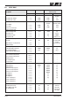
Manual DAS 72.1 4.1 Tare "ON":= Tare value stred non-volatile Tare "OFF": Tare value deleted at power off 4.2 EX-Modus "ON" Load cells connected with Zener barriers "OFF" Load cells connected without Zener barriers 3. Calibrate Zero to display "Zero” with manual setup of mV/V signal 2. Calibrate Zero with actual or external simulated input signal shows an overload (o) or an underload (u) 1 = 18 Hz to 8 = 0.25 Hz Typical setup: "4"=3 Hz Example: 0.0 (g) @ 4 mA • (02) Tare • (01) Zero 1.
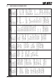
B.2 SETUP TABLE LED Display Pre Setup Menu Point < 1.1 > Value 0-oFF < 1.2 > < 1.3 > < 2.1 > 0.000 0.000 20000 < 2.2 > < 2.3 > < 2.4 > < 3.1.o > < 3.1.u > < 3.2 > < 3.3 > < 3.4 > < 4.1 > < 4.2 > 0.000 2.000 -99999 -9999 1 0 1 33.3 FIR < 4.3 > < 4.4 > < 5.1 > < 5.2 > < 5.3 > < 5.4 > < 6.1.1 > < 6.2.1 > < 6.3.1 > < 6.2 > < 6.3 > < 6.4 > < 7.1.1 > < 7.2.1 > < 7.3.1 > < 7.1.2 > < 7.2.2 > < 7.3.2 > < 7.1.3 > < 7.2.3 > < 7.3.3 > < 7.1.4 > < 7.2.4 > < 7.3.4 > < 8.1 > < 8.2 > < 8.3 > < 8.
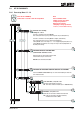
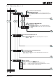
B.3 SET UP FLOWCHARTS B.3.1 Zero set up, Menu 1.1 - 1.4 SET UP Press the UP or DOWN key for more than 3 seconds to enter the Set-up Menu Inp.1 0 T Inp.1 Inp.2 TT 0 T Note: Recessed Enable Switch (Enables changes to be made to important parameters. Must be pressed before attempting to change parameters 1.1 to 1.3, 2.1 to 2.3 and 3.1 to 3.3) Automatic Zero Tracking Settings: 0 ... 255 d Function is swiched off at setting 00 000.
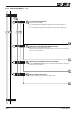
B.3.2 Span set up, Menu 2.1 - 2.4 Inp.1 0 Inp.2 T T T Inp.1 0 T SET THE SPAN CALIBRATION VALUE Two possibilities are available: A. Set the display value equivalent to the calibration weight, continue with step 2.2 or B. Use the mV/V signal derived from the load cell(s) test data, continue with step 2.3. Inp.1 0 Inp.1 Inp.2 T T 0 T CALIBRATE THE SPAN (CONVENTIONAL WEIGHING SYSTEM) Display shows the actual input signal in mV/V.
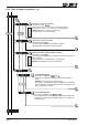
B.3.3 Display set up, Menu 3.1 - 3.4 Inp.1 0 T Inp.1 0 Inp.1 Inp.2 TT 0 T T SET THE DISPLAY OVER RANGE LIMIT (MAXIMUM VALUE +99 999) Use the and TT keys to set the maximum display value above which the display shows over range (all dashes in the top of the display). Inp.2 Inp.2 TT Inp.1 0 Inp.
B.3.4 Filter / no motion set up, Menu 4.1 - 4.4 Inp.1 0 T Inp.1 Inp.2 TT 0 T Set the low pass filter cut off frequency Set Range: 0 - 8 with Filter setting 18 Hz (4.1.1) to 0.25 Hz (4.1.8) with Filter type IIR. Filter setting 19.7 Hz (4.1.1) to 2.5 Hz (4.1.8) with Filter type FIR. Attention: Setting “0” (4.1.0) deactivates the Filter. See Paragraph C.4.5 for more information. 4.1.0 : : : 4.1.8 Inp.1 0 Inp.1 Inp.
B.3.5 Analogue output set up, Menu 5.1 - 5.4 Inp.1 0 Inp.2 T T T Inp.1 0 T Set the weight value at which 4 mA is send Setting with and TT Set the weight value at which 4 mA is send. Examples: Weighing range 3 000 kg and 3 000 d with 0/4...20 mA. Inp.2 Analogue output 4...20 mA: for 0 kg = 4 mA make setting 00 000. Analogue output 0...20 mA: for 600 kg = 4 mA make setting 00 600. Inp.1 0 Inp.2 T T Inp.
B.3.6 Logic input set up, Menu 6.1.3 - 6.3.4 The second digit coresponds with the input number 1 0 T 1 2 T T 0 Set the function for Logic Input “1” Possible settings: 00, 01 ,02 ,03 ,04 ,05 ,06 ,07, 08, 09, 10, 11, 12, 13, 14.
Logic input set up, Menu 6.1.3 - 6.3.4 (continued) 1 2 3 4 5 6 7 2 2 2 2 2 2 2 TT TT Manual DAS 72.1 8 T T No function T T No function 1 TT 0 T Check Logic Input “1” (6.1.1. must be set to “0” => 6.1.1.0) TT “In1 0.” Input is ”low” TT “In1 1.” Input is ”high” 1 0 1 0 T As per section 6.1 but for Logic Input “2” T As per section 6.
B.3.7 Logic output set up, Menu 7.1 - 7.
B.3.8 Data communication set up, menu 8.1 - 8.4 Inp.1 0 Inp.2 T T T Inp.1 0 T Set the Baud Rate for COMPORT (RS-422/485) Setting with and TT Inp.2 9 600 Baud 19 200 Baud 38 400 Baud 57 600 Baud 115 200 Baud Inp.1 0 Inp.2 T T Inp.1 0 T T Select either RS-422 or RS-485 Setting with and TT 422 = RS-422-Interface (use for single DAS application) 485 = RS-485-Interface (use for multiple DAS application in BUS) Inp.2 Inp.1 0 Inp.2 T T Inp.
B.3.9 Error codes The zero key is not enabled (See menu 1.1) Set final zero out of range. (You are trying to set a zero which is greater than ±2% of the Upper Display Limit) Excessive sensitivity requested. (The input signal is being divided into too many divisions i.e the size of each division is < 0.5 mV) The input signal is in excess of ± 2.
B.4 EXAMPLES B.4.1 Example 1, calibration procedure using weights 3 Leg tank or silo fitted with 3 off 1000 kg @ 2 mV/V load cells. Dead load 600 kg. Live range 2000 kg in 0.5 kg steps. It is assumed that the load cell system is connected to the DAS72.1 and the power is on. The maximum and minimum display values, display increment size and decimal point position should be defined prior to carrying out the calibration (See Menu 3). For this example the display maximum is defined as 2100.
Flowchart Example 1 Enter the Set-up menu Set the decimal point position Set the display step size Set the Display Upper Limit (Overload) Set the Display Lower Limit Calibrate the Zero point Set the Display value equal to the Calibration weight Calibrate the Span Calibration completed Page 18 SET UP 1. Press the UP or DOWN key for more than 3 seconds to enter the Set-up Menu 2. Press the recessed enable switch SET THE DECIMAL POINT POSITION (0, 0.0, 0.00, 0.000, 0.
B.4.2 Example 2, calibration procedure using load cell mV/V sensitivity and zero offset 3 Leg tank or silo fitted with 3 off 1000 kg @ 2mV/V load cells Dead load 600 kg. Live range 2000 kg in 0.5 kg steps. It is assumed that the load cell system is connected to the DAS72.1 and the power is on. The maximum and minimum display values, display increment size and decimal point position should be defined prior to carrying out the calibration (See Menu 3).
Flowchart Example 2 Enter the Set-up menu SET UP 1. Press the UP or DOWN key for more than 3 seconds to enter the Set-up Menu 2. Press the recessed enable switch Set the decimal point position SET THE DECIMAL POINT POSITION (0, 0.0, 0.00, 0.000, 0.0000) Use the UP or DOWN key to set the required decimal point position. Choose 0.0 Set the display step size SET THE DISPLAY STEP SIZE. (1, 2, 5, 10, 20, 50, 100, 200, 500) Use the UP or DOWN key to set the required display step size.
B.4.3 Example 3, calibration procedure using load cell mV/V sensitivity 3 Leg tank or silo fitted with 3 off 1000 kg @ 2 mV/V load cells. Dead load 600 kg. Live range 2000 kg in 0.5 kg steps. It is assumed that the load cell system is connected to the DAS 72.1 and the power is on. The maximum and minimum display values, display increment size and decimal point position should be defined prior to carrying out the calibration (See Menu 3). For this example the display maximum is defined as 2100.
Flowchart Example 3 Enter the Set-up menu SET UP 1. Press the UP or DOWN key for more than 3 seconds to enter the Set-up Menu 2. Press the recessed enable switch Set the decimal point position SET THE DECIMAL POINT POSITION (0, 0.0, 0.00, 0.000, 0.0000) Use the UP or DOWN key to set the required decimal point position. Choose 0.0 Set the display step size SET THE DISPLAY STEP SIZE. (1, 2, 5, 10, 20, 50, 100, 200, 500) Use the UP or DOWN key to set the required display step size.
C SETUP VIA SERIAL PORT C SETUP VIA SERIAL PORT C.1 COMMUNICATIONS & GETTING STARTED 23 24 C.1.1 Serial interface 24 C.1.2 Command Language 24 C.1.3 Setup baud rate / device address 25 C.1.4 Getting Started 25 C.2 WIRING DIAGRAM 26 C.3 COMMANDS SUMMARY 27 C.4 COMMANDS 29 C.5 CALIBRATION PROCEDURE. 54 C.6 USE IN “APPROVED” APPLICATIONS (only as information) 55 C.7 SOFTWARE (FIRMWARE) DOWNLOAD 56 Manual DAS 72.
C.1 COMMUNICATIONS & GETTING STARTED C.1.1 Serial interface Communicating with the DAS 72.1 digitizer is carried out via the RS422/RS485 port. The data format is the familiar 8/N/1 structure (8 data bits, no parity, 1 stop bit). Available baud rates via the RS422/RS485 port are as follows: 9.600, 19.200, 38.400, 57.600 or 115.200 baud. RS422 • Connection using a 4 wire technique. • Point-to-Point connection, i.e. no bus communication possible. • Half duplex setup (DX=0).
C.1.3 Setup baud rate / device address Baud rate Factory default: 9600 baud Address settings It is possible to set the network address of the device using the AD command. (Address range between 0 and 255). Setting the device address to 0 will set the continuously active mode, where the device becomes permanently active, and will listen and respond to any command on the bus, without the need for an OP xxx command. Factory default: Address 0 C.1.
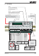
C.2 WIRING DIAGRAM Logic input 1 2 Inp.1 0 Depress 0 To Change Net 1.Zero 1.0/allow>0< 2.Calibrate 3.Set mV/V Logic output 1 2 2.Span 1.Set cal. ´n´ 2.Calibrate 3.Set mV/V 4.Disp.mV/V 3.Display 1.o/u limits´n´ 2.Step * ´n´ 3.Dec.point 4.Logic stats Load cell 5Vdc 80mA CL out 2 3 + 4 - - 5 6 7 4.Filter 1.fcut Hz 2.Algorithm 3.Update rate 4.Motion´n´ RS422/485 SET UP 6.Input 1/2/3 7.Outp. 1/2/3 8.Datacom. 5.CLout 1.Assign key 1.SPoint ´n´ 1.Baud rate 1.4mA=´n´ 2.20mA=´n´ 2. 2.Hyst.
Command AA AD AG AH AIn AL An AS AZ BR CE CG CI CL CM CS CZ DP DS DX FD FL FM GA GG GH GM GN GO GS GT GV GW Hn Short Description Get/set analog action Network address Absolute gain calibrate (TAC protected) Get/set analog high Action input n Get/set analog low Get/set setpoint n action Save analog output parameters Absolute zero calibrate (TAC protected) Baudrate Calibrate enable Calibrate gain (TAC protected) Calibrate min (TAC protected) Close all connections Calibrate max (TAC protected) Calibrate save
Page 28 Manual DAS 72.1 Command ID IN IO IS IV LI MT NR NT OM OP Pn RM RT RZ SD SG SH SM SN SO Sn SR SS ST SV SW SZ TE TH TL TR UR WP ZT Short Description Inform. device ID Read input status Read/Modify output status Inform. on device status Inform.
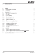
C.4 COMMANDS For better clarity, all commands are divided into groups as described on the following pages. C.4.1 System diagnosis Commands – ID, IV, IS, SR 30 C.4.2 Set up Commands – SD, MT, GA, TE, TR, TL, AI 31 C.4.3 Calibration Commands – CE, CI, CM, DS, DP, CZ, CG, AZ, AG, ZT, FD, CS 33 C.4.4 Motion detection Commands – NR, NT 37 C.4.5 Filter setting Commands – FM, FL, UR 38 C.4.6 Set Zero/Tare and Reset Zero/Tare Commands – SZ, RZ, ST, RT 40 C.4.
C.4.1 System diagnosis Commands – ID, IV, IS, SR Use these commands you get the DAS 72.1 type, firmware version or device status. These commands are sent without parameters. ID Request of device identify Master ( PC / PLC ) sends DAS 72.1 responds ID¿ D:7210 The response to this request gives the actual identity of the active device. This is particularly useful when trying to identify different device types on a bus. IV Request of firmware version Master ( PC / PLC ) sends DAS 72.
C.4.2 Set up Commands – SD, MT, GA, TE, TR, TL, AI Note: All setups should be stored with the WP command before power off. SD Start Delay 0 … 500 ms Set the delay between falling/rising edge of trigger pulse and start of measurement. Permitted values are 0 … 500 ms. Master ( PC / PLC ) sends DAS 72.
TR Trigger This command will start the measuring cycle in the same way as the hardware trigger input. TL Master ( PC / PLC ) sends DAS 72.1 responds Result TR¿ OK Trigger started Trigger Level Set the trigger level for rising edge start of measurement. Permitted values are in the range 0 … 99 999. Master ( PC / PLC ) sends DAS 72.
C.4.3 Calibration Commands – CE, CI, CM, DS, DP, CZ, CG, AZ, AG, ZT, FD, CS Note: TAC represents Traceable Access Code (calibration counter). CE TAC counter reading With this command you get the TAC counter reading or you can enable a calibration sequence. Master ( PC / PLC ) sends DAS 72.1 responds Result CE¿ E+00017 (example) Request: TAC-counter CE17 CE_17¿ OK Calibration sequence active This command must be issued PRIOR to any attempt to set the calibration parameters CZ, CG etc.
DS Display step size This command allows the output to step up or down by a unit other than 1. Permitted values are 1, 2, 5, 10, 20, 50, 100 and 200. DP Master ( PC / PLC ) sends DAS 72.
AZ Absolute zero point calibration The command AZ is used as reference point for all weight calculations and will setup in mV/V. Permitted values are ± 32 000 (= ± 3.2000 mV/V). Master ( PC / PLC ) sends DAS 72.1 responds Result AZ¿ Z+0.0005 Request: Zero point @ 0.0005 mV/V CE¿ E+00017 (example) Request: TAC-counter CE17 CE_17¿ OK Calibration sequence active AZ_00500¿ OK new: Zero point @ 0.0500 mV/V Factory default: 00 000 @ 0.0000 mV/V input signal.
FD Factory default settings This command puts the DAS 72.1 back to a known state. The data will be written to the EEPROM and the TAC will be incremented by 1. Note: All calibration and setup information will be lost by issuing this command! CS Master ( PC / PLC ) sends DAS 72.
C.4.4 Motion detection Commands – NR, NT The motion detection facility provides a means of disabling certain functions whenever a condition of instability, or “motion”, is detected. The “no-motion” or “stable” condition is achieved whenever the signal is steady for the period of time set by NT, during which it cannot fluctuate by more than NR increments.The stable condition activates the relevant bit of responses to “Info Status” (IS).
C.4.5 Filter setting Commands – FM, FL, UR Using the commands FM and FL, a digital filter type and strength can be set which will eliminate most of the unwanted disturbances. Please note that these filters are positioned immediately after the A/D Converter and therefore affect all aspects of the weighing operation. FM Filter Mode FIR / IIR Choose filter mode, permitted values are “0” for IIR and “1” for FIR. Master ( PC / PLC ) sends DAS 72.
Mode 1 Characteristic (FIR-Filter) FL Settling time to 3 dB Cut-off 20 dB damping 40 dB damping Damping in the 0.1% at frequency at frequency stopband (Hz) (Hz) (dB) (ms) (Hz) no filtering ** 47 19.7 48 64 >90 93 9.8 24 32 >90 140 6.5 16 21 >90 187 4.9 12 16 >90 233 3.9 10 13 >90 280 3.2 8 11 >90 327 2.8 7 9 >90 373 2.5 6 8 >90 0 1 2 3 4 5 6 7 8 Stopband Output rate max. (Hz) (samples/s) 600 600 300 200 150 120 100 85.
C.4.6 Set Zero/Tare and Reset Zero/Tare Commands – SZ, RZ, ST, RT The following commands allow you to set and reset zero and tare values. The zero set during calibration remains the ‘true zero’ but new ‘current zero’ can be set using the SZ command. If the SZ command is issued and accepted then all weight values will then be based on the new ‘current zero’. Please remember that zero value will be subject to the Zero tracking function if enabled.
ST Set Tare This command will activate the net weighing function by storing the current weight value as a tare. The weight signal must be “stable” within the limits set by NR (No Motion Range) and NT (No Motion Time) commands for the “signal stable” bit to be active and set tare command to be accepted. Master ( PC / PLC ) sends DAS 72.
C.4.7 Output Commands – GG, GN, GT, GS, GM, RM, GH, GO, GV, GW The following commands “Get” the Gross, Net, Tare, long weight and ADC (Sample) values from the DAS 72.1. GG GN GT GS Get Gross value Master ( PC / PLC ) sends DAS 72.1 responds Result GG¿ G+01.100 Gross 1 100 d Master ( PC / PLC ) sends DAS 72.1 responds Result GN¿ N+01.000 Net 1 000 d Master ( PC / PLC ) sends DAS 72.1 responds Result GT¿ T+000.
GO Get Peak to Peak value GV Master ( PC / PLC ) sends DAS 72.1 responds Result GO¿ O+01.000 Peak to Peak value 1 000 d Master ( PC / PLC ) sends DAS 72.1 responds Result GV¿ V+01.000 Valley value 1 000 d Get Valley value GW Get the “long” weight values (in a data string) Command for output of the current net weight, gross weight, scale status and checksum values. No decimal point is available in this data string. Master ( PC / PLC ) sends DAS 72.
C.4.8 Auto-transmit Commands – SG, SN, SW, SM, SH, SO, SV The following commands allow the gross weight or net weight values to be continuously sent. Continuous transmission starts as soon as the relevant command has been issued and finishes when any other valid command is accepted by the DAS 72.1. The data output rate will depend on the baud rate being used e.g. with a baud rate of 9600, approximately 100 readings per second can be transmitted. Note: The commands will only work if the DAS 72.
SO Peak to Peak value transmitted continuously This command gets the actual Peak to Peak value. This function has to be activated in menu 6.x.1 together with the command AIx SV Master ( PC / PLC ) sends DAS 72.1 responds Result SO¿ M+01.100 Peak to Peak value 1 100 d Valley value transmitted continuously This command gets the actual Valley value. This function has to be activated in menu 6.x.1 together with the command AIx Master ( PC / PLC ) sends DAS 72.1 responds Result SV¿ M+01.
C.4.9 Commands for external I/O control – IN, IO, OM, AI The DAS 72.1 has 3 independent logic inputs and 3 independent logic outputs. These inputs and outputs can be configured and controlled completely. The logic inputs can be read directly by the host application and the logic outputs can be fully controlled via the setpoint commands. The use of the setpoint commands (Sn, Hn, Pn, An) are explained in the following chapter 4.10.
OM Control of the logic outputs by the host application The logic outputs can be controlled by the host application (as opposed to the normal internal setpoints) if they are enabled by the IM command and the appropriate 4 digit code. Request Master ( PC / PLC ) sends DAS 72.
C.4.10 Setpoint Commands - Sn, Hn, Pn, An The DAS 72.1 has 3 logic outputs where the status is dependent on the weight value (setpoint). Each logic output can be assigned an independent setpoint value (Sn) with a corresponding hysteresis (Hn), switch action (Pn) and base (An – switch on the gross or the net weight). Sn Setpoint value for logic output 1, 2 or 3 Request / Setting Master ( PC / PLC ) sends DAS 72.
A2 Request / Set the Base for logic output 1,2 or 3 The A1 command defines the Base on which the setpoint value acts. If A1 is set to “0” then setpoint 1 acts on the unfiltered gross weight. If A1 is set to “1” then setpoint 1 acts on the unfiltered net weight.
C.4.11 Communication setup Commands – AD, CL, BR, DX, OP, LI NOTE: These settings will only take effect after a power on reset (remember to store the settings using the WP command before turning the power off.) AD Device address setup / request Setting the device address to 0 will cause the device to be permanently active, listening and responding to every command on the bus without the need for an OP command. Request Master ( PC / PLC ) sends DAS 72.
OP Device communication enable / request This command, if sent without parameters, requests the address or device number of the device active on the bus. If sent with parameters, this enables the device defined by the parameters. Request / Enable device communication Master ( PC / PLC ) sends DAS 72.
C.4.12 Commands Analogue Output 4 – 20 mA - AL, AH, AA The following commands must be saved in EEPROM by command AS. AA Sets the source which will be used by analogue output Possible selections for analogue output: AA = 0 gross weight AA = 1 net weight AA = 2 Peak value AA = 3 Average value AA = 4 Hold value AA = 5 Peak-to Peak value AA = 6 Valley value AA = 7 Hold value AA = 8 analogue output OFF Request / Set up analogue output: Master ( PC / PLC ) sends DAS 72.
C.4.13 Save parameters Commands – CS, WP, SS, AS, TH The setup and calibration parameters can be divided into 4 groups: • Calibration parameter: CZ, CG, CM, CI, DS, DP, ZT, are saved by the CS command. • Setup parameters (other than setpoint): FL, FM, NR, NT, BR, AD, DX etc are saved by the WP command. • Setpoint parameters: Sn, Hn, Pn, An are saved by the SS command. • Analogue output parameters: AA, AH, AL are saved by the AS command.
C.5 CALIBRATION PROCEDURE. The calibration interface features a “TRACEABLE ACCESS CODE” (TAC), as is required for use in “Approved” applications (see section 7, “USE IN APPROVED APPLICATIONS” for more details). This feature also ensures that access to the calibration functions is protected from inadvertent or unauthorised change. The following parameters are considered as CALIBRATION commands: • CE: Calibration Enable - returns the current TAC value. • CZ: Calibrate zero - sets the system zero point.
C.6 USE IN “APPROVED” APPLICATIONS (only as information) The term “approved” applies whenever the weighing application is intended to be used for “legal-for-trade” weighing - that is, money will change hands according to the weight result.
C.7 SOFTWARE (FIRMWARE) DOWNLOAD For software update of DAS 72.1 a Windows PC with RS 232 port and a converter RS232 to RS485/RS422 is required. The solder pads on the back side of PCB (see drawing below) must be closed before switching on. After download the solder pads must be opened again. A download is accomplished with help of our program “PROG78”. C.7.1 Firmware update for DAS 72.1 Mark II series First all necessary files (LduDownload.exe, prog78.a20, das72mII.
D CE DECLARATION OF CONFORMITY Flintec GmbH Bemannsbruch 9 D 74909 Meckesheim Konformitätserklärung Artikel: Geräte für digitale Datenerfassung von Wägezellen Hersteller: Flintec GmbH Typ/ Modell: QLC62.1 LDU68.X LDU69.1 DAS72.1 CAP76.1 LDU78.X Detaillierte Gerätebezeichnung: UIM62.5 (Anzeigeneinheit); QLJ67.x (Verteilerkasten); UA73.x (Adapter); UA77.