FLINTEC REMOTE DISPLAY TERMINAL FDT VERSION A/B TECHNICAL -REFERENCE MANUAL Flintec GmbH Bemannsbruch 9 74909 Meckesheim Germany Tel. +49 6226 92400 Fax. +49 6226 924099 www.flintec.net germany@flintec.net Document FDT – VERSION A/B – TECH. -REFERENCE MANUAL Date Code Rev. Page 05.04.99 FDT.
FLINTEC TABLE OF CONTENTS PAGE 1. INTRODUCTION 3 2. FRONT PANEL DESCRIPTION 4 INSTALLATION 6 MOUNTING WIRING AC POWER 6 6 3. 3.1. 3.2 3.3. 4. 6 OPERATING MODES 4.1 4.2 4.3 4.4 5. 7 7 7 8 8 REMOTE DISPLAY (Continuous weight input) MASTER DISPLAY AND KEYBOARD FOR FAD-1 /-4 SLAVE DISPLAY FOR FAD DUAL FAD MASTER MODE ( Scale A/B ) FDT CONFIGURATION FAD CONFIGURATION CUSTOM PRINT FORMATS SETUP AND CALIBRATION 9 9 11 15 6. FUNCTION MENU 16 7. ERRORS 18 COMMUNICATIONS 19 5.1. 5.2 5.
FLINTEC 1. INTRODUCTION FDT is a Remote Display Terminal specifically designed for use as remote weight indicator for Digital Junction Box weigh systems (FAD-1 or FAD-4). The unit maybe operated in the Master mode where it will poll all (max 30) FAD’s connected to it, or in the Slave mode where it will only display information from a selected FAD. Setup and Calibration of FAD’s is performed via FDT in the Master mode.
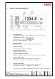
FLINTEC 2. FRONT PANEL DESCRIPTION 1. WEIGHT DISPLAY 6 digit LED for the display of measured weight (gross or net), and error messages. Digit height approx. 14mm. OVERARANGE is indicated by vvvvvv UNDER-RANGE is indicated by uuuuuu Scale not level will be indicated by E t i l t 2. NET INDICATOR If lights up when the scale has been tared and the display is in NET mode. 3. TARE INDICATOR It indicates that a tare value is being displayed. 4. NO MOTION INDICATOR It lights up when the scale is stable.
FLINTEC 8. 9. - 10. TARE KEY (toggle) It is used to tare the scale. Taring will be effective only if the scale is stable and within the weighing capacity. If the scale has already been tared depression of the key will cause the tare to be cancelled and the weight display to return to Gross mode. TARE RECALL KEY 11. ZERO / CLEAR ERROR / ESCAPE KEY It is used to reset the weight display to zero.
FLINTEC 3. INSTALLATION 3.1. Mounting The mounting location must be such that the instrument is not subject to excessive vibrations, heat or humidity. Avoid direct sunlight on the front of the instrument. The unit has to be installed at the right height to allow an easy reading of the display and keyboard operation. 3.2 Wiring Use 4 x 0,34 mm2 screened for RS232C connection and 2x0,34 mm2 twisted pair and shielded for RS485A connection.
FLINTEC 4. OPERATING MODES FDT may be configured according to the applications, to be operated in 4 different modes. 4.1 REMOTE DISPLAY - CONTINUOUS WEIGHT INPUT The unit displays information received from the serial port(s) according to LECW_2 format (P + 123.45 “CR”). RS485A may be received from port 1 (Version A or B). Baudrate and data bits are programmable in SETUP 3. RS232C may be received from port 2 (Version B only). Baudrate is fixed at 1200 baud.
FLINTEC 4.3 SLAVE DISPLAY FOR FAD The unit is connected in a FAD network. FAD unit(s) are scanned by a master unit which may be a personal computer or another FDT. The slave FDT will display all data (weight and messages) originating from the FAD with the same address. SETUP 1 2 3 REQUIREMENTS (9600, E, 7, 1, FAD address A) Don’t care Don’t care 3t = 03, 3b = 96, 3d = 17, 3E = 65, the rest don’t care.
FLINTEC 5. SET UP AND CALIBRATION The chapter refers to both the FDT and the FAD setting up. The FAD is configured with Fn 49 procedure. The RTD–52 is calibrated with Fn 46 procedure. For setup and calibration of the FAD the unit must have been connected and the correct communication protocol installed in both the FAD and FDT. It is advisable to leave the default settings [ (9600, E, 7, 1) , address A].
FLINTEC SETUP 2 2.t 2.d 2.E 2.L 2.r 2.A 2.F 2.1 2.2 2.3 2.4 2.5 2.6 2.7 2.8 (SERIAL PORT 2 / PRINT PARAMETERS) PRINT TYPE : PORT DISABLED. TICKET PRINTOUT (Date, time, Nr, weight). CONTINUOUS TRANSMISSION OF WEIGHT. TICKET GROSS, TARE, NET, (quadruple size). SINGLE LINE NUMBER AND GROSS, TARE, NET. HOST COMPUTER MODE. CUSTOM PRINTS . Format 1 in Gross (Max 512 b). Format 2 in Net (Max 512 b).
FLINTEC DIALOGUE STORE (Save in EEPROM) Press P to permanently save all the calibration data. Program exits setup / calibration and reinitialises. (up to 100.000 storage cycles allowed). The data will be stored in the FDT EEPROM. DIALOGUE INIT It initialises the FDT to factory default values. SET UP 1 SET UP 2 1.1 = 1 2.t = 01 2.1 = 0 1.2 = 1 2.d = 17 2.2 = 0 1.3 = 0 2.E = 65 2.3 = 0 1.4 = 0 2.L = 01 2.4 = 0 1.5 = 0 2.r = 00 2.5 = 0 1.6 = 1 2.A = 00 2.6 = 0 1.7 = 0 2.F = 00 2.7 = 0 1.8 = 0 2.8 = 0 1.
FLINTEC DIALOGUE PIN Enables activation or de-activation of the PINLOCK. Press I to scroll through Unloc , Loc . Unlock deactivates the PIN so that entry to setup and calibration menus is possible. However it does not override the hardware lock in the FAD. Press P to enter the displayed item. The display shows 000000. Key in the PIN number and press P . If the number entered was correct the display shows PASS briefly and returns to the calling menu.
FLINTEC MENU CAL (Scale calibration of FAD) Used for Zero, Span calibration and “corner” correction. Press P to enter the menu. Press I to scroll through S-CAL, E-CAL, CAL . Press P to enter the displayed dialogue. If the scale is calibrated for the first time or a loadcell is changed the sequence Corner, Zero, Span should be followed. Subsequent calibration may include only Zero or Zero and Span. Be aware that CAL does not automatically save the calibration constants in non volatile memory.
FLINTEC E-CAL DIALOGUE (Electronic calibration of FAD with mV/V from loadcell data sheets) Display shows CORNER. Press P to calibrate corners. Display shows 000000 . Enter the rated output (in mV/V) of loadcell in corner 1. (Example : If R. O of Loadcell 1= 1,9793 mV/V then enter 019793). The display shows CORNER.2 . Press P . Enter the rated output (in mV/V) of loadcell in corner 2. The display shows CORNER.3 . Press P . Enter the rated output (in mV/V) of loadcell in corner 3. The display shows CORNER.4 .
FLINTEC DIALOGUE INIT (Installation of Default Parameters) It downloads default calibration data for checking purposes. The weight display will act as a mV/V meter of the Loadcell output. Press P to activate the initialization procedure. Press O to exit the init mode. Be aware that the default parameters and calibration constants will remain in memory. If a subsequent StorE operation is performed previous calibration data will be lost. The default parameters are as follows : Par 2.P = 4 8.1-8.
FLINTEC 6. FUNCTION MENU The function menu enables the selection of a number of software programs indirectly. Press key A. Display shows Fn 00 . Key in the function code desired (using NUMSCROLL entry procedure). NUMSCROLL EDIT T = MOVE ONE DIGIT TO THE RIGHT (CYCLIC) I = INCREMENT FLASHING DIGIT P = ACCEPT DISPLAYED NUMBER The corresponding program will be activated.To exit the function selection, press P while Fn 00 is displayed. The following functions are available.
FLINTEC Fn 42 DOWNLOAD CUSTOM PRINT FORMAT . 2 The display shows For 2 indicating that it is ready to receive format 2. Begin the transmission. When the transmission ends press P . the display shows Prn 2 briefly when the format is saved in non volatile memory. A max of 512 bytes may be stored. If more characters are received they will be lost. Fn 46 SETUP OF FDT Fn 48 VIEW CALIBRATION AUDIT TRAIL COUNTER SEALEd is displayed if the CAL LOCK jumper inside the FAD is inserted. Press P to continue.
FLINTEC 7. ERRORS If an error occurs during the operation, it will be displayed in the form Err xx , where xx is the Error code. Program is halted. Press O momentarily to acknowledge the error and proceed as indicated in the error operator response. Errors may occur during set-up, programming, power-up and during operation.
FLINTEC 8. COMMUNICATIONS Version A has one communication port RS485A (SERIAL PORT 1). This is the port used for connection to FAD(s) and for networking. Version B has in addition to serial port 1 an RS232C port (SERIAL PORT 2), used for connection with printers or personal computers. 8.1 SERIAL PORT 1 (RS485A) The port operates in half duplex mode. Communication is based on “LESIP” master / slave serial interface protocol. (See “LESIP” with FAD appendix for details).
FLINTEC 8.2.2 PRINTER OUTPUT The weight and date time may be printed on. A serial printer connected with DTR protocol (See Annex A for connection details). Several print possibilities maybe selected in FDT SETUP 2. In addition two custom print formats may be created and downloaded to the FDT via the serial interface RS232. (Refer to function menu, chapter 6, Fn 41, Fn 42). SET UP 1 2 or or or 3 REQUIREMENTS Application specific 2.t = 01 (Date, time, number, weight) 2.
FLINTEC B. SCALE B Select scale B in a multi scale network. Master transmission: STX ADD B BCS2 BCS1 FDT response: STX ADD ACK BCS2 ETX BCS1 ETX C. SCALE A+B The sum of the weights on scales A and B is returned. Master transmission: STX ADD C BCS2 BCS1 ETX FDT response: STX ADD ACK BCS2 BCS1 ETX F. FORMAT CUSTOM DOWNLOAD The commands is used to download custom print formats to FDT.
FLINTEC P. PRINT The scale weight is printed in the internal electronic tally roll. The command returns the weight and sequence number of the Alibi memory. Master transmission: STX ADD P BCS2 BCS1 ETX FDT response: STX ADD P yyyyyy xxxx BCS2 BCS1 ETX If printing was succesful where xxxx = 4 digit serial number and yyyyyy: 6 digits weight including decimal point or ------ (empty) or ****** (corrupted data). or FDT response: STX ADD NACK BCS2 BCS1 ETX If print conditions were not met (Motion, -ve weight etc).
FLINTEC 9. 9.1. SPECIFICATIONS Environmental And Electrical Considerations AMBIENT TEMPERATURE HUMIDITY AIR VIBRATION PROTECTION ELECTROMAGNETIC / FIELDS POWER SUPPLY INCOMING AND/ OUTGOING SIGNALS NOTES 9.2. Technical Specifications DIGITAL PART VERSION A VERSION B SELF DIAGNOSTICS COMMUNICATIONS DISPLAY KEYBOARD ALIBI MEMORY EMC COMPATIBILITY DIMENSIONS / WEIGHT 9.3 Storage - 10 oC to + 70 oC. Operating - 10 oC to + 40 oC No direct sunlight to fall on the equipment.