WEIGHT INDICATOR FT-12 TECHNICAL MANUAL For Firmware Version 2.07 and higher Flintec GmbH Bemannsbruch 9 74909 Meckesheim GERMANY www.flintec.
Table of Contents: 1 Safety Instructions .........................................................................................................................................4 2 Declaration of Conformity .............................................................................................................................5 3 Overview..........................................................................................................................................................6 3.1 3.
9.3 Ethernet Option .......................................................................................................................................27 9.3.1 9.3.2 9.3.3 10 Other I/O Options......................................................................................................................................30 10.1 Analogue Output Option ......................................................................................................................30 10.1.1 10.1.2 10.
RIGHTS AND LIABILITIES All rights reserved. No part of this publication may be reproduced, stored in a retrieval system, or transmitted in any form or by any means, mechanical, photocopying, recording, or otherwise, without the prior written permission of Flintec GmbH No patent liability is assumed with respect to the use of the information contained herein. While every precaution has been taken in the preparation of this book, FLINTEC assumes no responsibility for errors or omissions.
2 DECLARATION OF CONFORMITY 0 EG-Konformitätserklärung EC-Declaration of Conformity Monat/Jahr: month/year: 07/2010 Hersteller: Manufacturer: Flintec GmbH Anschrift: Address: Bemannsbruch 9 D-74909 Meckesheim Deutschland / Germany Produktbezeichnung: Product name: FT-12 Wäge-Indikator / FT-12 Weight Indicator Das bezeichnete Produkt stimmt mit folgenden Vorschriften der Europäischen Richtlinien überein: This product confirms with the following regulations of the Directives of the European Communi
3 OVERVIEW The type FT-12 weight indicator is an economic and powerful state-of-the-art instrument. Its application covers any type of standard weighing process including dynamic weighing, check weighing and filling. The accurate and versatile instrument is available in different housings, meeting the industries demand for various environmental conditions. FT-12 is approved by Weights & Measures Authorities for use in Accuracy Class III applications with up to 10 000 intervals according to OIML R76.
3.
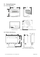
3.4 Housing Dimensions 3.4.1 Desk Type Housing 195 155 140 Desk type front view Desk type side view 187 179 POWER 230 VAC, 50Hz, RS232 C LOAD CELL OPTIO N S/N ANA □ □ BIN ETH □ □ INT MOD □ I/O3 3 □ I/O4 8 Desk type rear view Dimensions of Desk type housing with wall mount kit 3.4.2 Stainless Steel Housing 100 220 70 15 70 160 230 Stainless steel housing front view FT-12 Technical Manual, Rev. 1.
3.4.3 Panel Type Housing 174 175 68 90 Panel type front view Panel type side view 5,5 144 69 9 80 164 Sticker 5, mounting with 4x M4 Panel type rear view FT-12 Technical Manual, Rev. 1.
4 INSTALLATION AND COMMISSIONING PRECAUTION: Please read this manual carefully before energizing the indicator. Perform the commissioning operation according the procedure given here. Use trained personnel for cleaning, commissioning, checking and service of the indicator. The interference of untrained personnel may cause some unwanted damages or injures. Note: In this manual the term “Digital Load Cell“ will be refered to “DLC“. 4.
4.2.2 Standard Load Cell Connection The load cell wiring should be made carefully before energizing to avoid damages to the weight indicator and the load cells. The input resistance of the load cells that you want to connect should be more than 58 Ω. The sense pins of the instrument should be connected. In 4-wire installations the sense and excitation pins with the same polarity should be short circuited at the connector side.
5 FRONT PANEL AND KEYPAD 5.1 Weight Display and Status LEDs Figure 5.1 Front panel view of FT-12 The weight display of FT-12 is a 6 digit LED with 14 mm or 20 mm height. At the right side of the display there are 3 status LEDs for indicating “Gross”, “Net” and the standard unit “kg”.
5.2 Keypad The meaning of the front panel keys and the key functions are: FT-12 Meaning Power On/Off: This key is used for turning the instrument on or off. To switch off the key must be pressed and hold at least for 2 seconds. There is no On/Off key on panel type housings. Function : This key is used in combination with other keys to enter any function or to quit without saving. Info: This key is being used to view Total and CN information.
6 SETUP AND CALIBRATION 6.1 Basics 6.1.1 Basic Setup Keys on the Frontplate The symbols located on the lower right corner of each key indicate the function of the keys in the setup menu. The basic meanings of these keys are given in the table below.
6.2 Application Programmes Besides basic weighing the FT-12 indicator can be used in different common applications such as check weighing (over/under), peak hold, dynamic weighing (animal weighing) and automatic filling. The status LEDs located at the left side of the display and the digital I/O have different meanings according to the selected application mode. The meanings and the structure of the digital I/O are given in chapter 10. 6.2.
appears on the display. An alarm condition can be stopped by pressing the key. Starting or resetting the peak hold process can be also be done by a digital input. 6.2.4 Dynamic Weighing The dynamic weighing mode generally is used for weighing unstable objects like animals. First the threshold value (parameter [101]) and the time parameter (parameter [103]) should be defined in the setup mode (see chapter 6.2.6).
[105 ] Filling Type (only for filling application) 0 : Gross filling (factory default setting) 6.
[202 X] Power On Zero This parameter setting controls if after power-on the scale will get automatically zeroed if the weight is in the percentage of the zeroing range. If the weight is not in the zeroing range the display will show [E E E ] message until you press the .
6.5 Scale Calibration [3--] Calibration Block [30-] Calibration [300 ] Gravity This parameter should be used in the scale that will be verified in two stages by gravity adjustment (in legal metrologic applications). This parameter should not be touched in other applications. If you enter a value in this parameter before calibration (as six decimal digits, e.g. enter “798564” for “9.
will show the [WAıt ] message during the span adjustment under load. Approximately 10 seconds later the display will show the [SAvE ] message. You can confirm the “Save span adjustment under load” by pressing or cancel it by pressing the key. 7 MEMORY OPERATIONS 7.1 ID Memory FT-12 has two ID codes and the capability to assign clear-text names to them for print out. There are also 99 ID memories which can be shared between the two IDs in any way.
8 ALIBI MEMORY AND LEGAL METROLOGICAL RECORDS If the alibi memory is installed and activated, the indicator keeps the latest 149 764 weighing records in this memory. The recorded data can be viewed on the indicator’s display or exported via serial port. To find a definite record you have to enter parameter [802]. After reaching the desired record, the recorded data can be viewed in the display. If needed you can print this record together with the following 9 records by pressing the key.
9 COMMUNICATION 9.1 Overview about Communication Application Data export to PC (non-approved); Remote display; Remote control with ASCII entries (Z, T, C)* IndFace-Software; Process control (PLC, DCS, SCADA...
The pin configuration of the optional D-Sub 25-pin female connector is given below. Parameter [012] is set to is set to “2” “0” or “1” TxD1; Par. [01-] RxD1; Par. [01-] TxD2; Par. [02-] RTS1; Par. [01-] RxD2; Par. [02-] CTS1; Par. [01-] GND (RS 232C) R-; Par. [02-] R+; Par. [02-] T+; Par. [02-] +V; Par. [02-] Termination (RS 485) Termination (RS 485) A; Par. [02-] B; Par. [02-] T-; Par. [02-] +24V; 20 mA CL Shield Pin no.
1. Single Line You can send the data in single lines as shown below by pressing the key. 12/05/2005 14:47 DATE M S D TIME L S D 10 ID1 : 3 S P M S D 3 CN: 71 ID1 L S D 5 S P 3 M S D L S D Max. 34 G: 3.007 kg ID2 S P 3 M S D L S D Max. 34 T : CN S P 3 M S D GROSS L S D 9 1.001 kg S P M S D 3 2.006 kg TARE L S D 13 N: S P 3 M S D NET L S D 13 S P 3 M S D L S D 13 L F 1 C R 1 2.
[002 X] Handshake 0 : No Handshake 1 : Xon/Xoff [003 XX] Address The address range is 1 to 99. If you enter 0, the indicator will operate without an address. [004 X] Data Length and Parity 0 : 8 bit, no parity 1 : 7 bit, odd parity 2 : 7 bit, even parity [005 X] Checksum 0 : Checksum byte disabled 1 : Checksum byte enabled [01-] Serial Interface 2 This sub-block includes the parameters of the 2nd serial interface.
[04-] Printer If one of the serial interfaces is selected as printer, the label settings will be made in this sub-block. [040 X ] Print Out Format 1 : Single line 3 : EPL format 2 : Multi line 4 : Totalizing [041 X] Transfer of Date and Time via serial interface 0 : no 1 : yes [042 X] Transfer of CN (Consecutive no.
9.3 Ethernet Option FT-1x series indicators which are equipped with an Ethernet option can be connected to Ethernet TCP/IP or Modbus RTU over Ethernet networks as described below. 9.3.1 Electrical Connections The pin configuration of the RJ45 Ethernet connector is described below: 1 2 1: Link LED 2 Activity LED State Off Amber Green Pin no.
The Ethernet setup can be done by using the Ether X PC software. Note: For older instruments the configuration will be done by the Ethernet Device Installer PC software, see separate document on the Flintec Product-CD.
Frequently Asked Questions (FAQ) Question: Answer: The Ether X could not reach the FT-1x instrument. 1. Check the local network connection 2. Check if the IP address of the indicator is convenient for your network 3. Check the PC Ethernet output with other network instruments 4. Check the existence of the Ethernet related parameters in the instrument setup (see chapter 8.3.3). If you cannot not see these parameters in the setup, please check the proper installation of the Ethernet board. 5.
10 OTHER I/O OPTIONS 10.1 Analogue Output Option FT-12 can be equipped with 4 – 20 mA or 0 – 10 V analogue output option. The value of the analogue output changes in linear relationship to the displayed value.
10.2 Digital I/O Option 10.2.1 Electrical Connections It is possible to use control inputs and setpoint outputs if you add an optional digital I/O board (3 inputs and 3 outputs) to the instrument. The electrical connection of the inputs and outputs should be made as shown in Fig. 10.1. Figure 10.1 Digital I/O ports connection diagram Voltage 20 to 28 V DC 20 to 28 V DC Digital input Digital output Current Max. 30 mA Max.
0= 1= 2= 3= Disabled (factory default) (Output1 = Sp1), (Output2 = Sp2), (Output3 = Sp3) (Output1 = Sp1), (Output2 = Sp2), (Output3 = Stable) (Output1 = Sp1), (Output2 = Sp2), (Output3 = Error and Alarm) [131 X] Input 1 0 = Disabled (factory default) 3 = Clear 1 = Zero 4 = Print 2 = Tare 5 = Key lock Warning: This input will be used as tilt switch input for tilting applications (parameter [207] 0) [132 X] Input 2 0 = Disabled (factory default) 3 = Clear 1 = Zero 4 = Print 2 = Tare 5 = Key lock 1
11 DIAGNOSTICS The parameter block [9--] contains certain functions for checking and testing. [9--] Diagnostics The operations about checking and testing the instrument can be made here. [90-] Tests [900 ] Key Pad test In this step each key’s ASCII code will be shown on the display as you press the related key. By this way you can test if all the keys are functioning or not. Pressing “” key will take you to the next parameter.
APPENDIX 1: SETUP AND CALIBRATION MENUS FT-12 Setup and Calibration Menu 00 _ 0_ _ 000 001 SERIAL 1 INTERFACE 01 _ D.FORMAT 010 SERIAL 2 02 _ 011 D.FORMAT 020 SERIAL 3 04 _ 040 P.FORMAT 10 _ CONFİG 100 MODE 111 START UP 12 _ 120 FİLTER PARITY 120 0 120 045 103 MIN. PRT 104 PERIOD 105 ALARM FILLING TYPE Chapter 6.2 114 A. CLR TARE 120 NO FILTER ID2 PRT CTRL %END 113 STORE TARE F.ADJ 046 102 Chapter 9.2 044 ID1 L.FEED MIN WEIGHT 112 A.
APPENDIX 2: CONTINUES OUTPUT MODE DATA STRUCTURE The format and the definition of the continuous data output is given below. Status STX STA STB Indicated STC D5 D4 D3 D2 Tare D1 D0 D5 D4 D3 D2 D1 D0 CR CHK The definition of the status bytes STA, STB and STC is given below. Definition Table for Status Byte A Bits 0, 1 and 2 1 2 Decimal point 0 0 XXXXOO 0 0 XXXXXO 1 0 XXXXXX 1 0 XXXXX.X 0 1 XXXX.XX 0 1 XXX.XXX 1 1 XX.XXXX 1 1 X.
APPENDIX 3: HOST MODE DATA STRUCTURE If related parameters are adjusted for host communication, the weight indicator will be connected to your system in Host Mode. Functions “0x03” and “0x10” are supported. Read Hold Registers (0x03) This function code is being used to read the information in the register addresses which have been permitted to be read from holding registers.
Error Check Calculating: CSUM = 0 – (Slave_Add + Function + … + Last_data) (STX and CSUM are neglected while calculating CSUM) Tool for counting: 0 1 2 3 4 5 6 7 8 9 A B C D E F Example: @|01|10|0008|0001|02||0006|DE| To get the check sum (here FA) you have to sum following numbers first: 01+10+00+08+00+01+02+00+06 = 22 Now you have to subtracte 22 from 00: 00 - 22 = DE (Calculation examples: 00 – 10 = F0 ; 00 – 11 = EF) Display value Status Function (Read / Write) 03 (R) 03 (R) Tare
Examples: The commands will be used for an indicator which instrument address is set to 1. Reading weight data: Reading status data: Reading Tare data: Taring: @010300000002FA @010300020001F9 @010300030002F7 @011000080001020002E2 Loading 1500 value to Setpoint 1: 1.step: @0110000B000204000005DCFD 2.step: @011000080001020006DE Reading Setpoint 1 (SP1=1500): 1. step: @011000080001020007DD 2.
APPENDIX 4: MODBUS RTU DATA STRUCTURE If the instrument is programmed for Modbus, it can be used as a Modbus RTU slave on a RS485 communication line or on the Ethernet communication line. The Modbus slave adress is defined in the parameter [Address]. Function code “0x03” and function code “0x10” are supported. Read command Display value Modbus register 40 001 Function code 03 Register address 00,00 No.
Write command Control Modbus register 40 009 Function code 10 Register address 00,08 No.
Loading values “500”, “1000” and “1500” to setpoint 1, 2 and 3 1. step (load designated values to buffer memories) : 01, 10, 00,0B, 00,02, 04, 00,00,01,F4, B2,0B 01, 10, 00,0D, 00,02, 04, 00,00,03,E8, 32,88 01, 10, 00,0F, 00,02, 04, 00,00,05,DC, B1,26 2. step (activate buffer memories as setpoints) : 01, 10, 00,08, 00,01, 02, 00,06, 27,1A - Details of an example: Loading setpoint 1 with value “1500”; STEP1: loading value to buffer memory 01 FT address 10 Write function 00,0F Register address 00,02 No.
APPENDIX 5: ERROR TABLE The FT-1x weight indicators have been designed as very reliable and virtually error free instruments. However if an error occurs do not attempt to repair the equipment before you understand what caused the error. Note the problems you have with your instrument and the error messages shown on the display. Then try to solve the problem according to the error table given below.
APPENDIX 6: PARAMETER’S DEFAULT TABLE Parameter 0-- Interface 00- Serial Interface 1 0 Data format 1 Baud rate 2 Handshake 3 Address 4 Data length and parity 5 Checksum 01- Serial Interface 2 10 Data format 11 Baud rate 12 Handshake 13 Address 14 Data length and parity 15 Checksum 02- Serial Interface 3 20 Data format 21 Baud rate 22 Handshake 23 Address 24 Mode 25 Data length and parity 26 Checksum 03- Ethernet / Profibus 30 Ethernet data format 31 Ethernet address 04- Printer 40 Print out format 41 Date &
APPENDIX 7: CALIBRATION TABLE The n = maximum capacity / e values are given in the table below. Use this table for selecting your Max and e values. www.flintec.com FT-12 Technical Manual, Rev. 1.