
Manual


FT-12 Technical Manual, Rev. 1.35 November 2010
Page 23 of 44
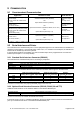
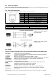
The pin configuration of the optional D-Sub 25-pin female connector is given below.
Parameter [012] Pin no. for stainless steel housing
is set to
“0” or “1”
is set to “2”
Pin no.
for desk and panel types
(D-Sub, 25-pin, female)
J10 connector
(Option 1)
JR1 / JR2 connector
(Option 2 or 3)
TxD1; Par. [01-] 2 8 15
RxD1; Par. [01-] 3 7 14
TxD2; Par. [02-] RTS1; Par. [01-] 4 3 10
RxD2; Par. [02-] CTS1; Par. [01-] 5 2 9
GND (RS 232C) 7 6-9 13
R-; Par. [02-] 8 Not used
R+; Par. [02-] 9 Not used
T+; Par. [02-] 10 Not used
+V; Par. [02-] 11 Not used
Termination (RS 485) 19 Not used
Termination (RS 485) 20 Not used
A; Par. [02-] 21 5 12
B; Par. [02-] 22 4 11
T-; Par. [02-] 24 Not used
+24V; 20 mA CL 25 Not used
Shield D25 body 1 1
The RS485 interface termination can be done by short circuiting pin no. 19 and 20 at the desk and panel type
enclosures or by jumper JP4 on the interface board within the stainless steel housing . These short circuits
terminate the line with an internal termination resistor of 100 .
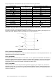
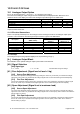
The 20mA CL ASCII output is disabled by default. The connections should be made as given in figure 9.1 for
enabling this output. (Enabled output is not available for 12 V DC instruments ).
9.2.3 Continuous Output Mode
The continuous output mode allows for a fast and continuous data export to connected peripheral devices. The
output data structure is described in Appendix 2.
9.2.4 Host Mode
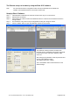
The indicator can communicate with a PC in host mode. You can upload or download data to the indicator by
adjusting the related interface parameters within the FLINTEC IndFace software or using the command sets
described in Appendix 3. This mode is convenient for process control applications which need not only the
weight data, but also require some uploads / downloads and status control.
9.2.5 Print Mode
In the print mode you can select the print formats (parameter group [04-], see chapter 9.2.6). This format –
preferably the single line – is convenient to use as weight data interface in legal for trade applications which
require recording to the Alibi memory. The print mode is not available for more than one interface (see also
overview in chapter 9.1).
25
11
10
24
9
8
FT-1x
Figure 9.1 20 mA CL ASCII interface connection