
Manual

FT-12 Technical Manual, Rev. 1.35 November 2010
Page 31 of 44
10.2 Digital I/O Option
10.2.1 Electrical Connections
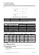
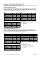
It is possible to use control inputs and setpoint outputs if you add an optional digital I/O board (3 inputs and 3
outputs) to the instrument. The electrical connection of the inputs and outputs should be made as shown in Fig.
10.1.
Figure 10.1 Digital I/O ports connection diagram
Voltage Current
Digital input 20 to 28 V DC Max. 30 mA
Digital output 20 to 28 V DC Max. 300 mA (sum of all 3 outputs)
The power for the digital I/O has to be supplied from an external power supply module.
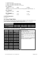
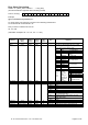
The pin layout of the parallel Input/Output connector is given below.
Pin no. for stainless steel housing
Definition
Pin no. for desk and panel types
(DB-Sub, 25-pin, female)
J10 connector (Option 1) JR1 / JR2 (Option 2 or 3)
0 V 13 1 1
+24V 12 - 24 - 25 2 2
Output 1 1 7 8
Output 2 3 8 7
Output 3 5 9 6
Input 1 11 3 10
Input 2 10 4 11
Input 3 9 5 12
Shield Connector Body Not Used Not Used
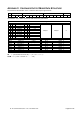
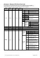
The meanings of the inputs and outputs varies according to the selected application mode. The input / output
tables for each mode is given below:
Mode Input1 Input2 Input3 Output1 Output2 Output3
Simple weighing Parameter
[131]
Parameter
[132]
Parameter
[133]
Parameter
[130]
Parameter
[130]
Parameter
[130]
Check weighing Parameter
[131]
Parameter
[132]
Parameter
[133]
OK
Out of
tolerance t2
Load stable and above
minimum value
Dynamic weighing Parameter
[131]
Start Reset Parameter
[130]
Parameter
[130]
Parameter
[130]
Peak hold Parameter
[131]
Start Reset Alarm In process End of process
Filling Parameter
[131]
Start Reset Coarse feed Fine feed End of filling
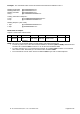
10.2.2 Setup
[1--] Configuration Block
In this block the parameters are located which are being used to set up the digital inputs and outputs.
[13-] Digital Inputs / Outputs
[130 X] Outputs
The outputs operate with respect to the displayed weight value. In the 3
rd
selection the Output 3 operates as Error
and Alarm output.