
Manual

FT-12 Technical Manual, Rev. 1.35 November 2010
Page 41 of 44
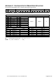
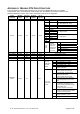
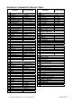
Loading values “500”, “1000” and “1500” to setpoint 1, 2 and 3
1. step (load designated values to buffer memories) : 01, 10, 00,0B, 00,02, 04, 00,00,01,F4, B2,0B
01, 10, 00,0D, 00,02, 04, 00,00,03,E8, 32,88
01, 10, 00,0F, 00,02, 04, 00,00,05,DC, B1,26
2. step (activate buffer memories as setpoints) : 01, 10, 00,08, 00,01, 02, 00,06, 27,1A
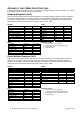
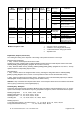
- Details of an example: Loading setpoint 1 with value “1500”; STEP1: loading value to buffer memory
01 10 00,0F 00,02 04 00,00,05,DC B1,26
FT
address
Write
function
Register
address
No. of
registers
Data byte
count
Data bytes:
Value 1500 in hex
CRC
checksum
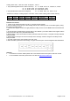
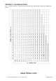
Calculate check sums:
1. Load a 16–bit register with FFFF hex (all 1’s). Call this the CRC register.
2. Exclusive OR the first 8–bit byte of the message with the low–order byte of the 16–bit CRC register, putting
the result in the CRC register.
3. Shift the CRC register one bit to the right (toward the LSB), fill a zero into the MSB. Extract and examine the
LSB.
4. (If the LSB was 0): Repeat Step 3 (another shift). (If the LSB was 1): Exclusive OR the CRC register with the
polynominal value A001 hex (1010 0000 0000 0001).
5. Repeat Steps 3 and 4 until 8 shifts have been performed. When this is done, a complete 8–bit byte will have
been processed.
6. Repeat Steps 2 through 5 for the next 8–bit byte of the message. Continue doing this until all bytes have
been processed.
7. The final contents of the CRC register is the CRC value.
8. When the CRC is placed into the message, its upper and lower bytes must be swapped as described below.
Attention:
For hardware connection details please refer to the related hardware descriptions within this manual
For more Modbus information please refer to the web site http://www.modbus.org