PC-BASED WEIGHING SYSTEM FlintWeigh II TECHNICAL MANUAL Flintec GmbH Bemannsbruch 9 74909 Meckesheim GERMANY www.flintec.
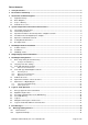
Table of Contents: 1. Safety Instructions ........................................................................................................................................ 3 2. Declaration of Conformity ............................................................................................................................ 4 3. Introduction and Block Diagrams ................................................................................................................ 5 3.1. 3.2. 3.3. 3.4.
RIGHTS AND LIABILITIES All rights reserved. No part of this publication may be reproduced, stored in a retrieval system, or transmitted in any form or by any means, mechanical, photocopying, recording, or otherwise, without the prior written permission of Flintec GmbH No patent liability is assumed with respect to the use of the information contained herein. While every precaution has been taken in the preparation of this book, FLINTEC assumes no responsibility for errors or omissions.
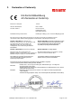
2.
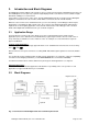
3. Introduction and Block Diagrams The W&M approved type FW-01 Scale Interface is the key component to integrate a Weighing System into your PC. FlintWeigh does not require any separate weight display and the scale interface assures, that the weight data will be reliably processed in the PC. It is possible to connect up to 2 scales (up to 16x type RC3D digital load cells respective 2x type LDU digital amplifiers) via RS485 to the scale interface, which will be connected to the PC via USB interface.
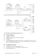
Type FW-01 Scale Interface Standard Load Cells KAL-4 Alibi memory 12 V DC Supply Digital I/O Fig. 3.2: Connection of standard load cells via KAL-4 junction box with integrated LDU Standard Load Cells KAL-4 Type FW-01 Scale Interface Alibi memory Standard Load Cells 12 V DC Supply KAL-4 Digital I/O Fig. 3.3: Block diagram with standard load cells and 2 scales 3.3.
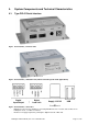
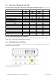
4. System Components and Technical Characteristics 4.1. Type FW-01 Scale Interface Fig.4.1 Scale interface, connector side Calibration lock Fig.4.2 Scale Interface; calibration lock (will be sealed in legal for trade applications) Digital Input/Output Digital Load cells Supply 12 V DC USB Fig.4.3 Scale Interface; connectors Digital load cell connector suitable for connecting RC3D load cells or one/two units of LDU xx.x in half-duplex mode, see LDU xx.
4.2. Technical Specifications GENERAL Scale interface ACCURACY Accuracy Class EU Type approved Intelligent interface with non-volatile memory for system parameters and calibration data III 10 000 intervals (single interval) or n x 3 000 intervals (multi range / multi interval) Approval no.
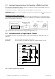
4.3. Important Information about the Operation of Digital Load Cells The connection of the digital load cells has to be done according the description in the KPFD-8 manual (see Flintec-CD, technical documents, manuals). It is allowed to connect up to 16 digital load cells (e.g. type RC3D) to the scale interface. IMPORTANT: If you connect more than 10 digital load cells, then it is mandatory to power all load cells from an external power supply.
4.5. Operation of Standard Load Cells The scale interface can be connected with up to two LDU amplifiers. Depending on the application – legal for trade scale or industrial application – it can be selected among various weighing modules. Weighing module type LDU 68.1 LDU 69.1 LDU 78.1 Accuracy class Certificate no. Intervals "n" acc. Kompmodeng: nind Internal resolution LDU 68.2 Not approved DK0199-R7610.04 Rev.1 10.000 DK0199-R7611.08 Rev.1 10.000 DK0199-R7610.08 Rev. 1 10.
4.7. Descriptive Plate The descriptive plate has to be placed on the weighing terminal’s enclosure. It must coincide with the digital descriptive plate within the FlintWeigh II software. The descriptive plate supplies following information: ► ► ► ► ► ► ► ► Owner and number of the EC type approval Version no. of the software incl. revision no./ check sum Serial no.
5. FlintWeigh II Software Installation The FlintWeigh II software displays the continuously measured weight value of the weighing system controller within a graphical window in a legal for trade quality. FlintWeigh II also provides an OLE interface. External programmes can access the data and information within FlintWeigh II by using OLE functions. All windows and control buttons are part of the OLE interface.
5.3. FlintWeigh II Files In the FlintWeigh II software directory you can find the following files (some files may be hidden or protected and therefore not visible): NW11F.EXE NW10.KEY NW10.INI FlintWeigh II main programme; can be used directly (EXE file) as weight display or for service and calibration purposes. In weighing mode the main programme can communicate to application programmes via its integrated OLE interface.
6. Weight Display and Control Buttons Fig. 7.1 : Weight display and control buttons (1) (2) (3) (4) (5) (6) (7) (8) (9) (10) (11) (12) Display window FlintWeigh II Logo Software version and checksum Weight value Weight unit* Service functions Displayed scale (no.
7. FlintWeigh II Configuration 7.1. Basic Setup during the Commissioning When you commission FlintWeigh II for the first time, following basic setup has to be done: • Sensor interface and Sensor type ( standard load cells OR digital load cells) • Scale system • Data memory • Interface to remote display and remote display type • Gravitational factor, if applicable These basic settings will be described in this chapter. Fig. 8.1 Weight display before commissioning Start the main programme ”NW11F.
7.1.1. Configure the Alibi Memory In legal for trade applications the recorded weighing results will be stored to an approved data memory, the so called alibi memory. Fig.8.3 Configure the alibi memory In the standard installation the data memory will be automatically created in the FlintWeigh II programme directory. Generally the location for the data memory can be selected freely, e.g. it is allowed to choose another local directory or any network drive.
7.2. Language and other Settings FlintWeigh II has some setup parameters, which can be set up before or after the commissioning. If you have configured a multi scale system, then first select the wished scale (“1” or “2”) in the weight display (Fig. 7.1). Fig. 8.
7.3. Scale with Standard Load Cells Important: The sensor type already has been set to “LDU” (see Fig. 8.2; Register “Communication“). If you have to configure a multi scale system, then select the wished scale no. ("1" or "2") within the weight display (Fig. 7.1). 7.3.1. Define the Scale Parameters Fig. 8.
Min. capacity: Minimum load of the scale (as a multiple of the scale interval e1) Test weight: Weight of the calibration weight (as a multiple of the scale interval e1) Changeover threshold 1/2: Only for multi-range / multi-interval scales: Transition points for range or interval (as a multiple of the scale interval e1) Important: For saving all scale parameter settings you have to close the window FlintWeigh II Settings afterwards. Now the weight display (Fig. 7.1) should show a random value.
Scale type: Setting Single-interval Multi-range Multi-interval Comment The scale has exactly one weighing range with a constant scale interval The scale has 2 or 3 weighing ranges with different scale intervals. If the current gros value of the measured weight falls within the next weighing range and larger scale interval (changeover threshold 1 and 2), then the larger scale interval remains active until the scale will be unloaded and will return to the zero point.
7.5. Calibrate the Scale Important: Before you can calibrate the scale you have to define the basic setup (see chapter 8.1) and the scale parameters (see chapter 8.3 respective 8.4). If you have to configure a multi scale system, then select the wished scale no. ("1" or "2") within the weight display (Fig. 7.1). 1. 2. 3. 4. Open the window “nWweigh Settings“ Open the register “Calibration” Unload the scale Click the button “Dead load“; this defines the current load status of the scale as the zero point.
7.6. Optional Linearisation of the Scale Curve The standard scale calibration may be supplemented by a linearisation with up to 5 correction points. Hereby the correction points have to be in a stricly increasing order, which is: Min. capacity < Point 1 < Point 2 < Point 3< Point 4 < Point 5 < Max. capacity of the scale Important: Before any linearisation you have to define the basic setup (see chapter 8.1), the scale parameters (see chapter 8.3 respective 8.
7.7. Optional Use of Digital Outputs After opening the service functions (window FlintWeigh II Settings) and selecting the register “Parameters“, you can assign a functionality to the digital outputs: Fig.8.11 Register “Parameters“ for defining the digital outputs Step 1: Select the source to control the output Allowed settings are Scale 1, Scale 2 and Combination. Step 2: Assign a functionality to the output Allowed settings are: Setting “Off“ “Limit“ “Traffic light“ 7.7.1.
7.7.2. Traffic Light Control The implementation of a traffic light control requires following setup: 1. Define the function “Limit“ for digital output 1 2. Define the function “Traffic Light” for digital output 2 3.
8. Legal for Trade Operation 8.1. EC Type-approval and Test Certificate See documents on the Flintec CD. 8.2. Digital Descriptive Plate The digital descriptive plate will be displayed after opening the service functions (window FlintWeigh II Settings) and selecting the register „Information“: Fig. 9.1 Digital descriptive plate The digital descriptive plate must conform to the physical descriptive plate.
8.4. Show Alibi Memory Fig. 9.4 Show alibi memory Click the button within the weight display The window FlintWeigh II long-time memory will be opened. Figure 9.5 Main window of the alibi memory First select the month and year of the time period to display If necessary it is also possible to display archived alibi data: search for the path to the file (“NWxxxx.MEM”*) and afterwards click the button “Show long-time memory”. Contents of the long-time memory: COM port no., scale no., record no.
8.6. Obligations with Legal for Trade Scales The operator is responsible for the first and all regularly recurrent official calibrations. Important: The official seal may only be broken by authorized qualified staff.
9. Error Messages Warnings Software Calibration A new software version is used. Elements of the calibration data have been changed. Important note: If a warning appears, the calibration data have to be saved again. Thereby the internal calibration counter will be incremented by one which is especially relevant in legal for trade applications. FlintWeigh Technical Manual, Rev. 3.
10. OLE Programming Interface The programming interface to an application programme is executed as an automation (OLE-) server for 32-bit Windows programmes (OLE = Object Linking and Embedding). The communication between any application programme and FlintWeigh II will be done exclusively by the following functions which are described below. 10.1.
Function Regist Description Register the current weight value – Format 1 Return value Format: string, 16 digits: “rrrrrr nnnnnnn dd w” with rrrrrr Record no., 6 digits Weight value including nnnnnnn decimal point, 7 digits dd Weight unit, 2 digits w Scale no., 1 digit Value range 000001, 000002, 000003... 0...800 000 g, kg, t, lb 1 (scale 1); 2 (scale 2); 3 (dual scale) Hint: Unused places within the weight value will be filled with spaces.
Function Status(w) Description Read scale status Parameter w Type Integer Use w = 1 (scale 1); w = 2 (scale 2); w = 3 (dual scale) Return value Value range Format: string, 31 digits: "AB_gggggggdd_tttttttdd_nnnnnndd" with 0 A Status bit 1 B Status bit 2 gggggggdd tttttttdd nnnnnnndd Gros value and unit Tare value and unit Net value and unit 2 (= 1) = No motion 1 2 (= 2) = Active tare (net indication) 2 2 (= 4) = Zero setting range 3 2 (= 8) = Accurate zero 4 2 (= 16) = Error 0 2 (= 1) = Zero cros
10.2. Application Example Example 1 – Visual Basic: Call of OLE function "Regist" in VB ------------------------------------------------------Dim scale As Object 'Create object and position the weight display '(only once in the programme during initialisation) Set scale = CreateObject("scale99.serv") Call scale.Position(0,0) 'Recording '(several times during normal operation) print_str = scale.Regist 'Stop communication '(only once in the programme before closing) Call scale.