Junction Box Type KAEX-4 TECHNICAL MANUAL Flintec GmbH Bemannsbruch 9 74909 Meckesheim GERMANY www.flintec.
RIGHTS AND LIABILITIES All rights reserved. No part of this publication may be reproduced, stored in a retrieval system, or transmitted in any form or by any means, mechanical, photocopying, recording, or otherwise, without the prior written permission of Flintec GmbH No patent liability is assumed with respect to the use of the information contained herein. While every precaution has been taken in the preparation of this book, FLINTEC assumes no responsibility for errors or omissions.
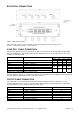
ELECTRICAL CONNECTIONS Figure 1: Dimensions in [mm] The connection sequence of the load cells should correspond to the corners of the scale, i.e Corner 1 = Load cell 1, Corner 2 = Load cell 2, etc. LOAD CELL CABLE CONNECTION First the cable gland must be loosened. Then you have to feed the load cell cable through the cable gland unless the shrink tube is fully disappeared in the box.
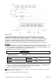
Figure 2: Wiring CORNER CORRECTION AT SCALES WITH FLINTEC LOAD CELLS Flintec load cells are manufactured with rather tight tolerances, so in most cases an additional corner correction is not required. The best conditions are achieved if you use load cells of the same class (Designation is done with capital letters A to I on the load cell package besides the type label). Hint: Corner errors can have a mechanical background, e.g. sloped mounting surface of the load cell. Procedure: 1.