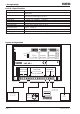
FLINTEC ...the right weigh Analogue Amplifier Type LAC 65.1 FLINTEC t (ms) L-P-FILTER % of FS-in Rel.Gain(x) SET SPAN SET ZERO Overflow -/+ ON 1-2 2 4 8 16 32 0-20/4-20 mA OFF 0-3 2,5 5 10 20 40 -/+ Int.PWR.ON 5 10 20 40 80 160 320 MANUAL LAC 65.1 1A Galvanically isolated SUPPLY PWR. 12-24 VDC 3W Load Cells OUTPUTS VEX 2,5V 425Hz <60mA +/-10V 20mA Exc Sen Sig Sig Sen Exc + + 0 0 + + + - - - Vo Io Document No G126 Rev2 UK www.flintec.com Manual LAC 65.
FLINTEC ...the right weigh LAC 65.1 Specifications Linearity Analogue input range Excitation Zero adjustment (Offset) Current output Voltage output Active filtering 40 dB / decade Temperature range Temperature effects Housing Power supply < 0.01 % ± 0.17 mV/V to 3.3 mV/V, gain adjustment by DIP switches and fine trimming potentiometer 2.5 V AC 425 Hz, for up to 8 off 350 Ohm load cells active sense for cable length up to 100 m ±80%, zero adjustment by DIP switches and fine trimming potentiometer 0 ...
FLINTEC ...the right weigh Calibration of the analogue output 1. Mounting the module The SG module has to be installed in a cabinet in compliance with (inter)national electrical regulations. Connection details are printed on the upper face of the amplifier housing. The amplifier module supports 6 wire technique. If you are using a 4 wire load cell, the “Exc +” and “Sen +” terminals must be shorted together as well as the “Exc –“ and “Sen –“ terminals. 2.
FLINTEC ...the right weigh 4. Output current (or voltage) adjustment Use a digital multimeter with at least a 5 digits display. Connect to current or voltage output as appropriate. Remark: The multimeter should have a current resolution of 0.01 mA to get a calibration accuracy of 0.05%. 5. Setting Zero With no load on the weighing system, use the Zero DIP-switches to initially set the zero value coarsely to approximately 4 mA (or whatever value you want at no load).