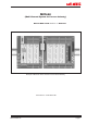
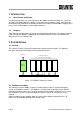
MCS-64 (Multi Channel System for Process Industry) Manual MCS-6 with Modbus on Ethernet C 0 1 2 3 C Mt1 C 0 1 2 3 C C 0 1 2 3 C C 0 1 2 3 C C 0 1 2 3 C C 0 1 2 3 C Mt2 9 1 Logic out Logic out ON DIP 1 2 3 4 Logic in Logic in PWR Com PWR Com In 0 In 1 In 1 In 1 In 2 In 2 In 2 In 2 In 3 In 3 In 3 In 3 In 3 Out 0 Out 0 Out 0 Out 0 Out 0 Out 1 Out 1 Out 1 Out 1 Out 1 Out 2 Out 2 Out 2 Out 2 Out 2 Out 3 Out 3 Out 3 Out 3 Out 3 Err Err Err Err Err In 1 In
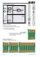
Components of MCS-64 in overview LDM 88.1 CGM 85,1 PGM 86.1 EGM 87,1 Base Board MB 89.1 Load Cell #1 RS 232 Service-Port LDM 88.1 #1 Fieldbus Gateway LDM 88.1 #2 - Profibus (PGM 68.1) - CANopen (CGM 85.1) - Ethernet (EGM 87.1) RS485 - Bus Load Cell #2 Load Cell #64 Extension Boards MB 89.2 MB 89.3 MB 89.4 LDM 88.
Weighing Processor LDM 88.1 The digital weighing processor LDM 88.1 is a load cell digitizing unit for precise measuring of loads in motion. • ± 18 bit resolution (±260 000 d) • Excitation 5 V DC / 50 mA • 2 400 Measurements/s internal, 600 Measurements/s external • mV/V calibration • 4 DI’s • 4 DO’s • RS 485 bus, 115.2 kBaud • Digital Filter (FIR and IIR) • for static or dynamic weighing processes • 3 Firmware versions Remote Control Output Start Filling Cycle Trigger Signal LDM 88.1 Digital Input 1 ..
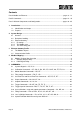
Contents Part A: Modbus on Ethernet.........................................................................................pages 6 - 13 Part B: Commands......................................................................................................pages 14 - 35 Part C: MCS-64 Components and Configuration........................................................pages 36 - 45 1. Introduction...................................................................................................................
6 MCS-64 Components and Configuration..........................................................................36 6.1 Base Board MB 89.1 for 1 Gateway and 2 LDM 88.x..................................................36 6.2 Extension Board MB 89.2 for 2 LDM 88.x ...................................................................37 6.3 Extension Board MB 89.3 for 4 LDM 88.x ...................................................................38 6.4 Extension Board MB 89.4 for 8 LDM 88.x .................
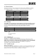
1. INTRODUCTION 1.1. Identification and Scope This document describes the system design for the Modbus on Ethernet (EGM 87.1) and up to 64 Load Cell Digitizing Modules (LDM88.x) using the Flintec backplane system. It describes the functionality of the backplane, the protocol used on the backplane and the Modbus mapping used to access the LDM88 modules via the EGM87 Gateway. 1.2.
2.3 Ethernet Gateway The Ethernet Gateway is using a 10/100baseT on RJ45 connection (IEEE 802.3u standard). The Gateway is essentially a server waiting for a node to connect to one of its services. Application stacks: Port 502 MBAP TCP IP 802.3 Modbus Application Layer Port 502 MBAP UDP IP 802.3 Setup Port 23 TCP IP 802.3 System stacks: (echo / ping) ICMP IP 802.3 (Dynamic IP addr.) DHCP IP 802.3 (Address Resolution) ARP 802.3 2.3.
3 ETHERNET GATEWAY PROFILE 3.1 The Modbus Objects All parameters and result data can be accessed in this way. Please note that many of the registers in the 2000 – 20FF range require a local backplane access cycle per register. Reading multiple registers in this range may produce a very long response time. Below is the preliminary Modbus Map. 3.2 Communication Profile The parameters which are critical for communication are determined in the communication profile.
4 MODBUS MAPPING The MBAP header “Unit Identifier” field is used to select a module in the backplane. Address 0 (zero) is reserved for broadcast. Address 1 to 64 is then used for direct communication with any LDM in the backplane using registers in the range 2000-2FFF (hex). Access to the gateway should use address 0xFF (255 dec) and registers in the range 3000-3FFF(hex).
4.1.2 LDM Register Map The register map for each LDM.
2061 Int16 1 R/W Bit commands. Functions regardless of the setting of the LDM selector register. Bit 1: Reset Zero (RZ) Bit 2: Set Zero (SZ) Bit 3: Reset Tare (RT) Bit 4: Set Tare (ST) Bit 5 – 7: unused Bit 8 –15: LDM# 2062 Int16 1 R/W 2063 Int16 1 R/W 2064 2065 Int16 Int16 1 1 R/W R/W Write a “1” to activate function, reads as “1” until command done Trigger: Functions regardless of the setting of the LDM selector register.
Page 0 – General Parameter Values Register 2100 2102 2104 2106 2108 210A 210C 210E 2110 2112 2114 2116 2118 211A 211C 211E 2120 2122 2124 Type Int32 Int32 Int32 Int32 Int32 Int32 Int32 Int32 Int32 Int32 Int32 Int32 Int32 Int32 Int32 Int32 Int32 Int32 Int32 Size 2 2 2 2 2 2 2 2 2 2 2 2 2 2 2 2 2 2 2 Access R/W R/W R/W R/W R/W R/W R/W R/W R/W R/W R/W R/W R/W R/W R/W R/W R/W R/W R/W General parameter values Analog action Analog high Analog low Filter setting Filter Factor Output status Input mask Measuring
Register 2320 2322 2324 2326 2328 Type Int32 Int32 Int32 Int32 Int32 Size 2 2 2 2 2 Access R/W R/W R/W R/W R/W Filling parameter values Secondary pre-fill level Timeout value in milliseconds Underweight post-fill time Tare interval Bag Rupture Blanking Page 3 – Check Weigher Parameter Values Register 2400 2402 2404 2406 2408 240A 240C 240E 2410 2412 2414 Type Int32 Int32 Int32 Int32 Int32 Int32 Int32 Int32 Int32 Int32 Int32 Size 2 2 2 2 2 2 2 2 2 2 2 Access R/W R/W R/W R/W R/W R/W R/W R/W R/W R/W R/
Part B 5 COMMANDS These pages describe the ASCII commands as they must be used by the DOP software. For each command the corresponding Modbus register and data types are shown in brackets [ ] for reference. 5.1 System diagnosis – ID, IV, IS ......................................................................................15 5.2 Calibration Commands – CE, CM, CI, DS, DP, CZ, CG AZ, AG, ZT, FD, CS.............16 5.3 Motion detection Commands – NR, NT..................................................
5.1 System diagnosis – ID, IV, IS Read these registers to get type, firmware version or device status of System MCS-64. ID Request of device identity [ Register = 202C, Type = Int32 ] Master (PC / PLC) sends ID Device responds D:8813 The response to this request gives the actual identity of the active device. This is particularly useful when trying to identify different device types on a bus.
5.2 Calibration Commands – CE, CM, CI, DS, DP, CZ, CG AZ, AG, ZT, FD, CS Note: TAC represents Traceable Access Code (calibration counter). CE TAC counter reading [ Register = 2204, Type = Int32 ] With this command you get the TAC counter reading or you can enable a calibration sequence.
DS Display step size [ Register = 2216, Type = Int32 ] This command allows the output to step up or down by a step size other than 1. Permitted values are 1, 2, 5, 10, 20, 50, 100 and 200.
AZ Absolute zero point calibration [ Register = 2202, Type = Int32 ] The command AZ is used as reference point for all weight calculations and will setup in mV/V. Permitted values are ± 32000 (= ± 3.2000 mV/V). Master (PC / PLC) sends Device responds AZ Z+0.0005 CE CE_17 E+00017 (example) OK AZ_00500 OK Result Request: Zero point @ 0.0005mV/V Request: TAC-counter CE 17 Calibration sequence active Setting: new: Zero point @ 0.0500 mV/V Factory default: 00000 @ 0.0000 mV/V input signal.
FD Factory default settings [ Register = 2266, Type = Int16, Value = 32768 ] This command puts the LDM88.x back to a known state. The data will be written to the EEPROM and the TAC will be incremented by 1.
5.3 Motion detection Commands – NR, NT The motion detection facility provides a means of disabling certain functions whenever a condition of instability, or “motion”, is detected. The “no-motion”, or “stable” condition is achieved whenever the signal is steady for the period of time set by NT, during which it cannot fluctuate by more than NR increments.The stable condition activates the relevant bit of responses to “Info Status” (IS).
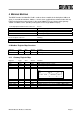
5.4 Filter setting Commands – FM, FL, UR Using the commands FM and FL, a digital filter type and strength can be set which will eliminate most of the unwanted disturbances. The command UR is used for the average building. Please note that these filters are positioned immediately after the A/D Converter and therefore affect all aspects of the weighing operation. FM Filter Mode FIR / IIR [Register = 2110, Type = Int32 ] Choose filter mode, permitted values are “0” for IIR and “1” for FIR.
Mode 1 Characteristic (FIR-Filter) 20 dB 40 dB Damping in Stopband Output rate FL Settling time 3 dB Cutto 0.1% off damping at damping at the max. frequency frequency stopband (Hz) (samples/s) (ms) (Hz) (Hz) (Hz) (dB) ** 0 no filtering 600 1 47 19.7 48 64 >90 >80 600 2 93 9.8 24 32 >90 >40 300 3 140 6.5 16 21 >90 >26 200 4 187 4.9 12 16 >90 >20 150 5 233 3.9 10 13 >90 >16 120 6 280 3.2 8 11 >90 >13 100 7 327 2.8 7 9 >90 >11 85.7 8 373 2.
5.5 Set Zero/Tare and Reset Zero/Tare Commands – SZ, RZ, ST, RT The following commands allow you to set and reset zero and tare values. The zero set during calibration remains the ‘true zero’ but new ‘current zero’ can be set using the SZ command. If the SZ command is issued and accepted then all weight values will then be based on the new ‘current zero’. Please remember that zero value will be subject to the Zero tracking function if enabled.
ST Set Tare [ Register 2061, Type = Int16: Value = LDM# * 256 + 016 ] This command will activate the net weighing function by storing the current weight value as a tare. The weight signal must be “stable” within the limits set by NR (No Motion Range) and NT (No Motion Time) commands for the “signal stable” bit to be active and set tare command to be accepted.
5.6 Output Commands – GG, GN, GT, GS The following commands “Get” the Gross, Net, Tare and ADC (Sample) values from the LDM88.x are available in floating point and integer respectively. GG Get Gross value Master (PC / PLC) sends GG GN Result Gros weight 1.100 d [ Register = 2002, Type = Float ] [ Register = 2022, Type = Int32 ] Device responds G+01.000 Get Tare value Master (PC / PLC) sends GT GS Device responds G+01.
5.7 Setpoint Commands - Sn, Hn, An The LDM88.x has 4 setpoints where the status depends on the weight value. Each of them can be assigned as an independent setpoint value (Sn) with a corresponding hysteresis/switch action (Hn) and base (An – switch on the gross or the net weight).
Example of positive hysteresis of 100 kg (H1 = +1.00) on a setpoint of 20.00 kg (lines 3 & 4 of table above): When the weight is increasing between 0 kg and 19.99 kg the setpoint is “OFF”. Once the weight increases above 19.99 kg then the setpoint is “ON”. The setpoint will switch “OFF” again when the weight value drops below 19.00 kg.
5.8 Trigger Commands – SD, MT, GA, TE, TR, TL Remark: These commands are only available in firmware 88.183 (see time diagram page 30); the TR command is also available in the 88.184 firmware. Note: All setups should be stored with the WP command before power off. SD Start Delay 0 … 500 ms [ Register = 2412, Type = Int32 ] [ Register = 211A, Type = Int32 ] Set the delay between falling/rising edge of trigger pulse and start of measurement. Value range is 0 … 500 ms.
TL Trigger Level [ Register = 2400, Type = Int32 ] [ Register = 211E, Type = Int32 ] Set the trigger level for rising edge start of measurement. Permitted values are in the range 0…262143. Master (PC / PLC) sends TL TL_1000 Device responds T+99999 OK Result Request: TL=99999 Setting: TL=1000 With regard to the trigger commands SD and MT, a check weighing will automatically start when the weight overshoots by e.g. 1.000d (increments), e.g. 100,0 g.
Page 30 Manual MSC-64: Modbus on Ethernet Tare Window TW M (g) MT Measuring Time SD Start Delay TI Tare Interval Trigger point choose 1 of 3: 1. Light barrier or 2. TR command or 3. TL Trigger Level Typical Checkweigher Signal : 1 (full duplex) : 0 (max. 600 meas./s) : 65535 (off) : 65535 (off) TW TI SD MT FL : 10 d : 200 ms : 100 ms : 300 ms : 2 (8 Hz) t Typ.
5.9 Trigger Special Commands– RW, TT, TS, DT, TW, TI, HT Remark: These commands are only available in firmware 88.183 (see time diagram page 33). Note: All setups should be stored with the WP command before power off. RW Re-Trigger Window [ Register = 2404, Type = Int32 ] Set the re-trigger window in counts (digits) without decimal point. If the weight relative to the current average value changes by more than the RW value the average cycle will be restarted using TT as measuring time.
TW Tare Window [ Register = 240A, Type = Int32 ] Set the Tare Window in counts (digits) without decimal point. Tare window (TW) allows an automatic Tare update. If TW = 0 this function is not active. If TW = 100, this means a new tare value will be taken when the net average weight of an empty scale is within 100 counts or division of zero. The new average tare value is calculated over the average tare time defined by TI. If the tare average is outside tare window, the tare will not be updated.
5.10 Save calibration, setup and setpoint parameters Commands – CS, WP, SS The setup and calibration parameters can be divided into 3 groups: • Calibration parameters: CZ, CG, DS, DP & ZT are saved by the CS command. • Setup parameters (other than setpoint): FL, FM, NR, NT, BR, AD, etc. are saved by the WP command. • Setpoint parameters: Sn, Hn and An are saved by the SS command.
5.11 Filling Commands – PD1 to PD21, DI, SC, AC, GD, DT, SD Remark: These commands are only available in firmware 88.184. Note: All setups should be stored with the SD command before power off. A separate description of these commands is availble as pdf-file. Please contact germany@flintec.net. 5.12 Loss in Weight Commands – PL1 to PL5, LC, LI, GF, GR, GM, SL Remark: These commands are only available in firmware 88.185. Note: All setups should be stored with the SL command before power off.
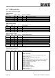
6 MCS-64 COMPONENTS AND CONFIGURATION These pages describe the MCS-64 components and address setup for the extension boards. 6.1 Base Board MB 89.1 for 1 Gateway and 2 LDM 88.
6.2 Extension Board MB 89.2 for 2 LDM 88.
6.3 Extension Board MB 89.3 for 4 LDM 88.
Load Cells HP ExcSenSigSig+ Sen+ Exc+ ExcSenSigSig+ Sen+ Exc+ ExcSenSigSig+ Sen+ Exc+ 8 load cell terminal blocks J14 J12 J13 8 DI terminal blocks ExcSenSigSig+ Sen+ Exc+ ExcSenSigSig+ Sen+ Exc+ J11 C 0 1 2 3 C ExcSenSigSig+ Sen+ Exc+ J11 C 0 1 2 3 C ExcSenSigSig+ Sen+ Exc+ ExcSenSigSig+ Sen+ Exc+ J12 C 0 1 2 3 C C 0 1 2 3 C 8 DO terminal blocks C 0 1 2 3 C J12 C 0 1 2 3 C J13 C 0 1 2 3 C J14 C 0 1 2 3 C R1 + BC R2 470uF Logic in Logic out 6.4 Extension Board MB 89.
6.5 Address setup guide extension boards for 1 – 16 channels DIP switch setting see table below 2 ch. MB 89.1 ON OFF 1 2 3 4 5 4 ch. MB 89.1 MB 89.2 ON OFF 1 ON 2 3 4 5 OFF 1 2 3 4 5 6 ch. MB 89.1 MB 89.2 MB 89.2 ON ON OFF 1 2 3 4 OFF 1 5 2 3 4 2 3 4 8 ch. MB 89.1 MB 89.3 MB 89.2 ON OFF 1 ON ON 2 3 4 5 OFF 1 OFF 1 2 3 4 5 10 ch. MB 89.1 MB 89.2 ON OFF 1 MB 89.2 MB 89.3 ON ON 2 3 4 5 OFF 1 2 3 OFF 1 4 2 3 4 2 3 4 12 ch. MB 89.
6.6 Address setup guide extension boards for up to 32 channels DIP switch setting see table below ON 2 3 4 5 ON ON ON OFF 1 OFF 1 2 3 OFF 1 4 2 3 OFF 1 2 3 4 5 18 ch. MB 89.1 MB 89.2 MB 89.3 ON ON ON OFF 1 2 3 4 5 MB 89.2 MB 89.4 OFF 1 2 3 ON OFF 1 4 2 3 OFF 1 2 3 4 2 3 4 20 ch. MB 89.1 MB 89.2 MB 89.3 ON MB 89.4 ON ON OFF 1 2 3 4 5 MB 89.3 OFF 1 2 3 ON OFF 1 4 2 3 OFF 1 ON OFF1 2 3 4 5 22 ch. MB 89.1 MB 89.2 MB 89.3 ON MB 89.
0 + 12 ... 24 V DC - V DC Service Port RS 232C 5 Y Page 42 J7 J8 Shield J9 C 0 1 2 3 C HP Load Cells + 470uF BC Logic in Logic out Common (+VDC or -VDC) C 0 1 2 3 C Input 0 PC6-20kg-C3 Common (C) “-VDC” Light barrier must give a “+VDC” peak Trigger: - measuring signal or - connect light barrier @ input 0 For checkweigher application 6.
Manual MCS-64: Modbus on Ethernet 0 + 12 ... 24 V DC pos. Pulse Input 1 Tare Service Port RS 232C 5 Y Input 0 Check Zero J7 J8 Screen J9 C 0 1 2 3 C HP Load Cells + 470uF BC Logic in Logic out Output 1 fine feed + - C 0 1 2 3 C Valve max. 45V 500 mA - + GND PC6-20kg-C3 Remark: Valves switch to + V DC Output 0 coarse feed 6.
6.9 LDM 88.1 – Digital Input / Digital Output - Outputs LDM 88.1 < 35 V DC / 500 mA or < 25 V AC / 500 mA (50/60 Hz) Common is “-” V DC Common is “+” V DC Output 1 0 Output 1 0 Output 2 1 Output 2 1 Output 3 2 Output 3 2 Output 4 3 Common C + - Output 4 3 Common C + Inputs LDM 88.1 opto-isolated 10 ... 30 V DC, max.
6.10 Firmware Versions LDM 88.183 for check weighing and dosing/filling of non fluid products LDM 88.184 for dosing/filling of fluids LDM 88.185 for mass flow, trend and totalizing of fluids/powder 6.11 DOP software for Windows 2000/XP For an easy setup or as a service tool you can use the DOP-Software; actual version DOP 2.0.2. This software supports you for calibration, easy setup of all available commands, recording data over time and display the graphs. For more details see separate manual.
DECLARATION OF CONFORMITY ß 0 Product: Multi Channel Weighing System Manufacturers designation: MCS-64 Manufacturer: Flintec GmbH, Bemannsbruch 9, DE74909 Meckesheim, Germany As manufacturer of the article we herewith assures that the article meets the requirements of the European legislation covering technical instruments, the standard safety rules, other safeguard regulations as well as the generally approved rules for technical safety, environmental protection and electromagnetic compatibility.