
Instruction Manual

Manual MCS-64: Modbus on Ethernet
Page 21
5.4 Filter setting Commands – FM, FL, UR
Using the commands FM and FL, a digital filter type and strength can be set which will eliminate
most of the unwanted disturbances. The command UR is used for the average building. Please
note that these filters are positioned immediately after the A/D Converter and therefore affect all
aspects of the weighing operation.
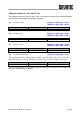
FM Filter Mode FIR / IIR [Register = 2110, Type = Int32 ]
Choose filter mode, permitted values are “0” for IIR and “1” for FIR.
Master (PC / PLC) sends Device responds Result
FM M+00001
Request: FM = 1 (FIR)
FM_0 OK
Setting: FM = 0 (IIR)
WP OK
Setting saved
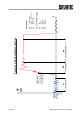
The digital IIR filter works as a low-pass filter of 2
nd
order with Gaussian characteristic, damping
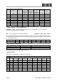
is 40 dB/decade; see table mode 0. The digital FIR filter works as a low-pass filter with quick
response; damping see table mode 1. Factory default: 0
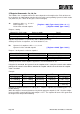
FL Filter settings [Register = 2106, Type = Int32 ]
Command for setup cut off frequency, permitted values are 0 … 8.
Master (PC / PLC) sends Device responds Result
FL F+00003
Request: FL = 3
FL_1 OK
Setting: FL = 1
WP OK
Setting saved
Filter values can be chosen between 0 and 8, see table below.
FL= 0 means no filter in mode 0 or 1 (command FM).
Factory default: 3
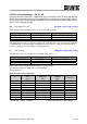
Mode 0 Characteristic (IIR-Filter)
FL
Settling time to
0.1%
(ms)
3dB Cut-off
frequency
(Hz)
Damping
@300Hz
(dB)
Output-rate*
(samples/s)
0 no filtering
**
600
1 55 18 57 600
2 122 8 78 600
3 242 4 96 600
4 322 3 104 600
5 482 2 114 600
6 963 1 132 600
7 1923 0.5 149 600
8 3847 0.25 164 600
* Output-rate = 600/2
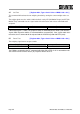
UR
samples/s ** Antialiasing filter 17 Hz @ 60 dB/dec