User's Guide Wireless TRMS Multimeter Model EX540 1 EX540 V1.
Introduction This meter measures AC/DC Voltage, AC/DC Current, Resistance, Capacitance, Frequency (electrical & electronic), Duty Cycle, Diode Test, and Continuity plus Thermocouple Temperature. It can store and recall data. It features a waterproof, rugged design for heavy duty use. This meter can transmit data wirelessly when linked to a PC. Proper use and care of this meter will provide many years of reliable service.
SAFETY INSTRUCTIONS This meter has been designed for safe use, but must be operated with caution. The rules listed below must be carefully followed for safe operation. 1.
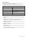
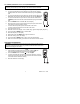
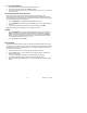
Controls and Jacks 1. 40,000 count LCD display 2. STORE() button 8 13. REL(+) button Note: Tilt stand and battery compartment are on rear of unit. Symbols and Annunciators •))) n µ m A k F M Ω Hz % AC DC ºF MAX N0.
Operating Instructions WARNING: Risk of electrocution. High-voltage circuits, both AC and DC, are very dangerous and should be measured with great care. 1. ALWAYS turn the function switch to the OFF position when the meter is not in use. 2. If “OL” appears in the display during a measurement, the value exceeds the range you have selected. Change to a higher range. DC VOLTAGE MEASUREMENTS CAUTION: Do not measure DC voltages if a motor on the circuit is being switched ON or OFF.
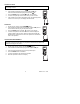
mV VOLTAGE MEASUREMENTS CAUTION: Do not measure mV voltages if a motor on the circuit is being switched ON or OFF. Large voltage surges may occur that can damage the meter. 1. 2. Set the function switch to the mV position. Press the MODE button to indicate “DC”.or ““AC ”, or in AC range press EXIT for two seconds and chose ”AC+DC” 3. Insert the black test lead banana plug into the negative COM jack. Insert the red test lead banana plug into the positive V jack. 4.
AC CURRENT (FREQUENCY, DUTY CYCLE) MEASUREMENTS CAUTION: Do not make 20A current measurements for longer than 30 seconds. Exceeding 30 seconds may cause damage to the meter and/or the test leads. 1. 2. 3. 4. 5. 6. 7. 8. 9. 10. 11. 12. 13. 14. 11. Insert the black test lead banana plug into the negative COM jack. For current measurements up to 4000µA AC, set the function switch to the µA position and insert the red test lead banana plug into the µA/mA jack.
CONTINUITY CHECK WARNING: To avoid electric shock, never measure continuity on circuits or wires that have voltage on them. 1. 2. 3. 4. 5. Set the function switch to the Ω CAP position. Insert the black lead banana plug into the negative COM jack. Insert the red test lead banana plug into the positive Ω jack. Press the MODE button to indicate“ "and “Ω” on the display Touch the test probe tips to the circuit or wire you wish to check.
TEMPERATURE MEASUREMENTS 1. Set the function switch to the Temp position. 2. Insert the Temperature Probe into the input jacks, making sure to observe the correct polarity. 3. Press the MODE button to indicate “ºF” or “ºC” 4. Touch the Temperature Probe head to the part whose temperature you wish to measure. Keep the probe touching the part under test until the reading stabilizes (about 30 seconds). 5. Read the temperature in the display.
% 4 – 20mA MEASUREMENTS 1. Set up and connect as described for DC mA measurements. 2. Set the rotary function switch to the 4-20mA% position. 3. The meter will display loop current as a % with 0mA=-25%, 4mA=0%, 20mA=100%, and 24mA=125%. AUTORANGING/MANUAL RANGE SELECTION When the meter is first turned on, it automatically goes into AutoRanging. This automatically selects the best range for the measurements being made and is generally the best mode for most measurements.
DISPLAY BACKLIGHT Press the key to turn the backlight on. The backlight will automatically turn off after SET time. Press the EXIT button to exit the backlight on mode. HOLD The hold function freezes the reading in the display. Press the HOLD key momentarily to activate or to exit the HOLD function. PEAK HOLD The Peak Hold function captures the peak AC or DC voltage or current. The meter can capture negative or positive peaks as fast as 1 millisecond in duration.
PC WIRELESS COMMUNICATION: 1. Install and launch the pc software 2. Press and Hold the backlight button for two seconds to enter RF wireless transmit mode. 3. 4. 5. 6. will appear on the display. The RF icon When communication is established, the RF icon on the display will blink and the led indicator on the receiver will also blink. Once per second, the data will be displayed on the pc screen, plotted and inserted into a list.
Maintenance WARNING: To avoid electric shock, disconnect the test leads from any source of voltage before removing the back cover or the battery or fuse covers. WARNING: To avoid electric shock, do not operate your meter until the battery and fuse covers are in place and fastened securely. This MultiMeter is designed to provide years of dependable service, if the following care instructions are performed: 1. KEEP THE METER DRY. If it gets wet, wipe it off. 2. USE AND STORE THE METER IN NORMAL TEMPERATURES.
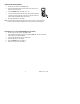
REPLACING THE FUSES WARNING: To avoid electric shock, disconnect the test leads from any source of voltage before removing the meter cover. 1. Disconnect the test leads from the meter. 2. Remove the protective rubber holster. 3. Remove the battery cover (two “B” screws) and the battery. 4. Remove the six “A” screws securing the rear cover. 5. Gently remove the old fuse and install the new fuse into the holder. 6. Always use a fuse of the proper size and value (0.
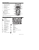
Specifications Function DC Voltage Range 400mV 4V 40V 400V 1000V Resolution 0.01mV 0.0001V 0.001V 0.01V 0.1V Accuracy ±(0.06% reading + 2 digits) ±(0.1% reading + 2 digits) AC Voltage 400mV 0.01mV ±(1.0% reading + 4digits) (AC+DC) 4V 0.0001V 50 to 1000Hz 40V 0.001V ±(1.0% reading + 3digits) 400V 0.01V 1000V 0.1V All AC voltage ranges are specified from 5% of range to 100% of range DC Current 400µA 0.01µA 4000µA 0.1µA ±(1.0% reading + 3 digits) 40mA 0.001mA 400mA 0.01mA 10A 0.
Function Resistance Capacitance Frequency (electronic) Frequency (electrical) Duty Cycle Range Resolution 400Ω 0.01Ω 4kΩ 0.0001kΩ 40kΩ 0.001kΩ 400kΩ 0.01kΩ 4MΩ 0.001MΩ 40MΩ 40nF 400nF 0.001MΩ 0.001nF 0.01nF 4µF 0.0001µF 40µF 0.001µF Accuracy ±(0.3% reading + 9 digits) ±(0.3% reading + 4 digits) ±(2.0% reading + 10 digits) ±(3.5% reading + 40 digits) ±(3.5% reading + 10 digits) 400µF 0.01µF 4000µF 0.1µF ±(5% reading + 10 digits) 40mF 0.001mF 40Hz 0.001Hz 400Hz 0.01Hz 4kHz 0.
Enclosure Shock (Drop Test) Diode Test Double molded, waterproof 6.5 feet (2 meters) Test current of 0.9mA maximum, open circuit voltage 2.8V DC typical Storage capacity 9999 records RF transmit distance 10 meters (approx) Transmitter Frequency 915MHz Continuity Check Audible signal will sound if the resistance is less than 35Ω (approx.), test current <0.
Warranty EXTECH INSTRUMENTS CORPORATION (A FLIR COMPANY) warrants this instrument to be free of defects in parts and workmanship for one year from date of shipment (a six month limited warranty applies to sensors and cables). If it should become necessary to return the instrument for service during or beyond the warranty period, contact the Customer Service Department at (781) 890-7440 ext. 210 for authorization or visit our website www.extech.com for contact information.