
User's Manual


7 EX540 V1.0 2/09
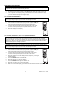
AC CURRENT (FREQUENCY, DUTY CYCLE) MEASUREMENTS
CAUTION: Do not make 20A current measurements for longer than 30 seconds.
Exceeding 30 seconds may cause damage to the meter and/or the test leads.
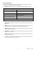
1. Insert the black test lead banana plug into the negative COM jack.
2. For current measurements up to 4000µA AC, set the function switch to
the µA position and insert the red test lead banana plug into the µA/mA
jack.
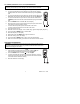
3. For current measurements up to 400mA AC, set the function switch to the
mA position and insert the red test lead banana plug into the µA/mA jack.
4. For current measurements up to 20A AC, set the function switch to the
10A/HZ/% position and insert the red test lead banana plug into the 10A
jack.
5. Press the MODE button to indicate “AC” on the display.
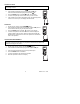
6. Remove power from the circuit under test, then open up the circuit at the
point where you wish to measure current.
7. Touch the black test probe tip to the neutral side of the circuit.
Touch the red test probe tip to the “hot” side of the circuit.
8. Apply power to the circuit.
9. Read the current in the display. In the 10AAC range, right auxiliary display frequency.
10. Press and hold the MODE button to indicate “Hz”.
11. Read the frequency in the display.
12. Momentarily press the MODE button again to indicate “%”.
13. Read the % duty cycle in the display.
14. Press and hold the MODE button to return to current measurement.
11. With ACA in the main display, press EXIT for 2 seconds to measure AC+DC.
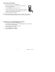
RESISTANCE MEASUREMENTS
WARNING: To avoid electric shock, disconnect power to the unit under test and
discharge all capacitors before taking any resistance measurements. Remove the
batteries and unplug the line cords.
1. Set the function switch to the Ω CAP position.
2. Insert the black test lead banana plug into the negative COM jack.
Insert the red test lead banana plug into the positive Ω jack.
3. Press the MODE button to indicate “Ω” on the display.
4. Touch the test probe tips across the circuit or part under test. It is best
to disconnect one side of the part under test so the rest of the circuit will
not interfere with the resistance reading.
5. Read the resistance in the display.