
User's Manual Part 2
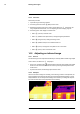
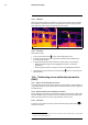
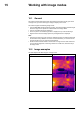
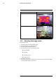
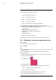
Table Of Contents
- 15 Working with image modes
- 16 Working with measurement tools
- 16.1 General
- 16.2 Adding/removing measurement tools
- 16.3 Working with user presets
- 16.4 Resizing or moving a measurement tool
- 16.5 Changing object parameters
- 16.6 Displaying values in the result table and displaying a graph
- 16.7 Creating and setting up a difference calculation
- 16.8 Setting a measurement alarm
- 17 Fetching data from external FLIR meters
- 18 Working with color alarms and isotherms
- 19 Annotating images
- 20 Programming the camera (time lapse)
- 21 Recording video clips
- 22 Screening alarm
- 23 Changing settings
- 24 Technical data
- 24.1 Online field-of-view calculator
- 24.2 Note about technical data
- 24.3 Note about authoritative versions
- 24.4 FLIR T600 15° (incl. Wi-Fi and Ext. cal.)
- 24.5 FLIR T600 15° (incl. Wi-Fi)
- 24.6 FLIR T600 25° (incl. Wi-Fi and Ext. cal.)
- 24.7 FLIR T600 25° (incl. Wi-Fi)
- 24.8 FLIR T600 25° and 15° w/case
- 24.9 FLIR T600 25° and 45° w/case
- 24.10 FLIR T600 45° (incl. Wi-Fi and Ext. cal.)
- 24.11 FLIR T600 45° (incl. Wi-Fi)
- 24.12 FLIR T600bx 25° (incl. Wi-Fi and Ext. cal.)
- 24.13 FLIR T600bx 25° (incl. Wi-Fi)
- 24.14 FLIR T600bx 45° (incl. Wi-Fi and Ext. cal.)
- 24.15 FLIR T600bx 45° (incl. Wi-Fi)
- 24.16 FLIR T610 15° (incl. Wi-Fi)
- 24.17 FLIR T610 25° (incl. Wi-Fi)
- 24.18 FLIR T610 45° (incl. Wi-Fi)
- 24.19 FLIR T620 15° (incl. Wi-Fi and Ext. cal.)
- 24.20 FLIR T620 15° (incl. Wi-Fi)
- 24.21 FLIR T620 25° (incl. Wi-Fi and Ext. cal.)
- 24.22 FLIR T620 25° (incl. Wi-Fi)
- 24.23 FLIR T620 25° and 15° (incl. Wi-Fi)
- 24.24 FLIR T620 25° and 45° (incl. Wi-Fi)
- 24.25 FLIR T620 45° (incl. Wi-Fi and Ext. cal.)
- 24.26 FLIR T620 45° (incl. Wi-Fi)
- 24.27 FLIR T620bx 15° (incl. Wi-Fi and Ext. cal.)
- 24.28 FLIR T620bx 15° (incl. Wi-Fi)
- 24.29 FLIR T620bx 25° (incl. Wi-Fi and Ext. cal.)
- 24.30 FLIR T620bx 25° (incl. Wi-Fi)
- 24.31 FLIR T620bx 45° (incl. Wi-Fi and Ext. cal.)
- 24.32 FLIR T620bx 45° (incl. Wi-Fi)
- 24.33 FLIR T630 15° (incl. Wi-Fi)
- 24.34 FLIR T630 25° (incl. Wi-Fi)
- 24.35 FLIR T630 45° (incl. Wi-Fi)
- 24.36 FLIR T630sc 15° (incl. Wi-Fi)
- 24.37 FLIR T630sc 25° (incl. Wi-Fi)
- 24.38 FLIR T630sc 25° and 45° w/case
- 24.39 FLIR T630sc 45° (incl. Wi-Fi)
- 24.40 FLIR T640 15° (incl. Wi-Fi and Ext. cal.)
- 24.41 FLIR T640 15° (incl. Wi-Fi)
- 24.42 FLIR T640 25° (incl. Wi-Fi and Ext. cal.)
- 24.43 FLIR T640 25° (incl. Wi-Fi)
- 24.44 FLIR T640 25° and 15° (incl. Wi-Fi)
- 24.45 FLIR T640 25° and 45° (incl. Wi-Fi)
- 24.46 FLIR T640 45° (incl. Wi-Fi and Ext. cal.)
- 24.47 FLIR T640 45° (incl. Wi-Fi)
- 24.48 FLIR T640bx 15° (incl. Wi-Fi and Ext. cal.)
- 24.49 FLIR T640bx 15° (incl. Wi-Fi)
- 24.50 FLIR T640bx 25° (incl. Wi-Fi and Ext. cal.)
- 24.51 FLIR T640bx 25° (incl. Wi-Fi)
- 24.52 FLIR T640bx 45° (incl. Wi-Fi and Ext. cal.)
- 24.53 FLIR T640bx 45° (incl. Wi-Fi)
- 24.54 FLIR T650sc 15° (incl. Wi-Fi)
- 24.55 FLIR T650sc 25° (incl. Wi-Fi)
- 24.56 FLIR T650sc 25° and 15° w/case
- 24.57 FLIR T650sc 25° and 45° w/case
- 24.58 FLIR T650sc 45° (incl. Wi-Fi)
- 24.59 FLIR T660 15° (incl. Wi-Fi and Ext. cal.)
- 24.60 FLIR T660 15° (incl. Wi-Fi)
- 24.61 FLIR T660 25° (incl. Wi-Fi and Ext. cal.)
- 24.62 FLIR T660 25° (incl. Wi-Fi)
- 24.63 FLIR T660 25° and 15° w/case
- 24.64 FLIR T660 25° and 45° w/case
- 24.65 FLIR T660 45° (incl. Wi-Fi and Ext. cal.)

Working with images14
14.5.3 Example 2
Here are two infrared images of an isolator in a power line. To make it easier to analyze
the temperature variations in the isolator, the temperature scale in the right image has
been changed to values close to the temperature of the isolator.
Automatic Manual
14.5.4 Procedure
Follow this procedure:
1. In live mode, push the button
to enter manual image adjust mode.
2. To change the temperature scale minimum and maximum limits simultaneously,
move the joystick up/down.
3. To change the temperature scale minimum or maximum limit, do the following:
• Move the joystick left/right to select (highlight) the maximum or minimum
temperature.
• Move the joystick up/down to change the value of the highlighted temperature.
4. (Optional step). In preview/edit mode, push the button
to perform a one-shot auto-
adjust sequence.
14.6 Performing a non-uniformity correction
(NUC)
14.6.1 What is a non-uniformity correction?
A non-uniformity correction is an image correction carried out by the camera software to
compensate for different sensitivities of detector elements and other optical and geomet-
rical disturbances
1
.
14.6.2 When to perform a non-uniformity correction?
The non-uniformity correction process should be carried out whenever the output image
becomes spatially noisy. The output can become spatially noisy when the ambient tem-
perature changes (such as from day to night operation, and vice versa).
14.6.3 Procedure
To perform a non-uniformity correction, push and hold the Image archive button
for
more than 2 seconds.
#T559880; r. AL/45866/46124; en-US
37
1. Definition from the impending international adoption of DIN 54190-3 (Non-destructive testing – Thermographic
testing – Part 3: Terms and definitions).