
User Manual

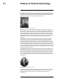

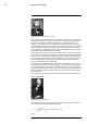
Table Of Contents
- 1 Disclaimers
- 2 Safety information
- 3 Notice to user
- 4 Customer help
- 5 Introduction
- 6 Quick start guide
- 7 A note about ergonomics
- 8 Camera parts
- 9 Screen elements
- 10 Navigating the menu system
- 11 Handling the camera
- 11.1 Charging the battery
- 11.2 Turning on the camera
- 11.3 Turning off the camera
- 11.4 Adjusting the viewfinder’s dioptric correction
- 11.5 Adjusting the angle of the lens
- 11.6 Adjusting the infrared camera focus manually
- 11.7 Autofocusing the infrared camera
- 11.8 Continuous autofocus
- 11.9 Operating the laser pointer
- 11.10 Using the digital zoom function
- 11.11 Assigning functions to the programmable buttons
- 11.12 Using the camera lamp as a flash
- 11.13 Changing lenses
- 11.14 Using the close-up lens
- 11.15 Changing the viewfinder eyecup
- 11.16 Calibrating the compass
- 12 Saving and working with images
- 13 Achieving a good image
- 14 Working with image modes
- 15 Working with measurement tools
- 15.1 General
- 15.2 Adding/removing measurement tools
- 15.3 Working with user presets
- 15.4 Resizing or moving a measurement tool
- 15.5 Changing object parameters
- 15.6 Displaying values in the result table and displaying a graph
- 15.7 Creating and setting up a difference calculation
- 15.8 Setting a measurement alarm
- 16 Working with color alarms and isotherms
- 17 Annotating images
- 18 Programming the camera (time lapse)
- 19 Recording video clips
- 20 Screening alarm
- 21 Pairing Bluetooth devices
- 22 Configuring Wi-Fi
- 23 Changing settings
- 24 Technical data
- 24.1 Online field-of-view calculator
- 24.2 Note about technical data
- 24.3 Note about authoritative versions
- 24.4 FLIR T1020 12°
- 24.5 FLIR T1020 28°
- 24.6 FLIR T1020 45°
- 24.7 FLIR T1030sc 12°
- 24.8 FLIR T1030sc 28°
- 24.9 FLIR T1030sc 45°
- 24.10 FLIR T1040 12°
- 24.11 FLIR T1040 28°
- 24.12 FLIR T1040 45°
- 24.13 FLIR T1050sc 12°
- 24.14 FLIR T1050sc 28°
- 24.15 FLIR T1050sc 45°
- 25 Mechanical drawings
- 26 Cleaning the camera
- 27 Application examples
- 28 About FLIR Systems
- 29 Glossary
- 30 Thermographic measurement techniques
- 31 History of infrared technology
- 32 Theory of thermography
- 33 The measurement formula
- 34 Emissivity tables

History of infrared technology
31
When Herschel revealed his discovery, he referred to this new portion of the electromag-
netic spectrum as the ‘thermometrical spectrum’. The radiation itself he sometimes re-
ferred to as ‘dark heat’, or simply ‘the invisible rays’. Ironically, and contrary to popular
opinion, it wasn't Herschel who originated the term ‘infrared’. The word only began to ap-
pear in print around 75 years later, and it is still unclear who should receive credit as the
originator.
Herschel’s use of glass in the prism of his original experiment led to some early contro-
versies with his contemporaries about the actual existence of the infrared wavelengths.
Different investigators, in attempting to confirm his work, used various types of glass in-
discriminately, having different transparencies in the infrared. Through his later experi-
ments, Herschel was aware of the limited transparency of glass to the newly-discovered
thermal radiation, and he was forced to conclude that optics for the infrared would prob-
ably be doomed to the use of reflective elements exclusively (i.e. plane and curved mir-
rors). Fortunately, this proved to be true only until 1830, when the Italian investigator,
Melloni, made his great discovery that naturally occurring rock salt (NaCl) – which was
available in large enough natural crystals to be made into lenses and prisms – is remark-
ably transparent to the infrared. The result was that rock salt became the principal infra-
red optical material, and remained so for the next hundred years, until the art of synthetic
crystal growing was mastered in the 1930’s.
Figure 31.3 Macedonio Melloni (1798–1854)
Thermometers, as radiation detectors, remained unchallenged until 1829, the year Nobili
invented the thermocouple. (Herschel’s own thermometer could be read to 0.2 °C
(0.036 °F), and later models were able to be read to 0.05 °C (0.09 °F)). Then a break-
through occurred; Melloni connected a number of thermocouples in series to form the
first thermopile. The new device was at least 40 times as sensitive as the best thermome-
ter of the day for detecting heat radiation – capable of detecting the heat from a person
standing three meters away.
The first so-called ‘heat-picture’ became possible in 1840, the result of work by Sir John
Herschel, son of the discoverer of the infrared and a famous astronomer in his own right.
Based upon the differential evaporation of a thin film of oil when exposed to a heat pat-
tern focused upon it, the thermal image could be seen by reflected light where the inter-
ference effects of the oil film made the image visible to the eye. Sir John also managed
to obtain a primitive record of the thermal image on paper, which he called a
‘thermograph’.
#T559954; r.28105/28105; en-US
163