
User Manual

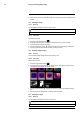
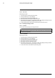
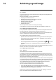
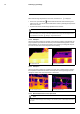
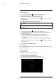
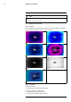
Table Of Contents
- 1 Disclaimers
- 2 Safety information
- 3 Notice to user
- 4 Customer help
- 5 Introduction
- 6 Quick start guide
- 7 A note about ergonomics
- 8 Camera parts
- 9 Screen elements
- 10 Navigating the menu system
- 11 Handling the camera
- 11.1 Charging the battery
- 11.2 Turning on the camera
- 11.3 Turning off the camera
- 11.4 Adjusting the viewfinder’s dioptric correction
- 11.5 Adjusting the angle of the lens
- 11.6 Adjusting the infrared camera focus manually
- 11.7 Autofocusing the infrared camera
- 11.8 Continuous autofocus
- 11.9 Operating the laser pointer
- 11.10 Using the digital zoom function
- 11.11 Assigning functions to the programmable buttons
- 11.12 Using the camera lamp as a flash
- 11.13 Changing lenses
- 11.14 Using the close-up lens
- 11.15 Changing the viewfinder eyecup
- 11.16 Calibrating the compass
- 12 Saving and working with images
- 13 Achieving a good image
- 14 Working with image modes
- 15 Working with measurement tools
- 15.1 General
- 15.2 Adding/removing measurement tools
- 15.3 Working with user presets
- 15.4 Resizing or moving a measurement tool
- 15.5 Changing object parameters
- 15.6 Displaying values in the result table and displaying a graph
- 15.7 Creating and setting up a difference calculation
- 15.8 Setting a measurement alarm
- 16 Working with color alarms and isotherms
- 17 Annotating images
- 18 Programming the camera (time lapse)
- 19 Recording video clips
- 20 Screening alarm
- 21 Pairing Bluetooth devices
- 22 Configuring Wi-Fi
- 23 Changing settings
- 24 Technical data
- 24.1 Online field-of-view calculator
- 24.2 Note about technical data
- 24.3 Note about authoritative versions
- 24.4 FLIR T1020 12°
- 24.5 FLIR T1020 28°
- 24.6 FLIR T1020 45°
- 24.7 FLIR T1030sc 12°
- 24.8 FLIR T1030sc 28°
- 24.9 FLIR T1030sc 45°
- 24.10 FLIR T1040 12°
- 24.11 FLIR T1040 28°
- 24.12 FLIR T1040 45°
- 24.13 FLIR T1050sc 12°
- 24.14 FLIR T1050sc 28°
- 24.15 FLIR T1050sc 45°
- 25 Mechanical drawings
- 26 Cleaning the camera
- 27 Application examples
- 28 About FLIR Systems
- 29 Glossary
- 30 Thermographic measurement techniques
- 31 History of infrared technology
- 32 Theory of thermography
- 33 The measurement formula
- 34 Emissivity tables

Achieving a good image13
When manual image adjustment mode is active, the status icon is displayed.
• In live mode, push the button
to switch between automatic and manual image ad-
justment modes. You can also switch between the modes by touching the temperature
scale on the screen.
• In preview/edit mode, manual image adjustment mode is active.
NOTE
You can also assign the function Auto adjust the manual temperature scale to one of the programmable
buttons, which allows you to perform an automatic adjustment of the image while remaining in manual
image adjustment mode. Select
(Settings) > Programmable buttons.
13.3.2 Example 1
Here are two infrared images of a building. In the left image, which is auto-adjusted, the
large temperature span between the clear sky and the heated building makes a correct
analysis difficult. You can analyze the building in more detail if you change the tempera-
ture scale to values close to the temperature of the building.
Auto adjustment mode Manual adjustment mode
13.3.3 Example 2
Here are two infrared images of an isolator in a power line. To make it easier to analyze
the temperature variations in the isolator, the temperature in the right image has been
changed to values close to the temperature of the isolator.
Automatic adjustment mode Manual adjustment mode
13.3.4 Manual adjustment in Level, Span mode
NOTE
This procedure assumes that you have configured the camera to do manual image adjustments in Lev-
el, Span mode. Select Settings > Device settings > User interface options > Manual adjustment mode =
Level, Span.
#T559954; r.28105/28105; en-US
45