
User Guide
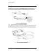
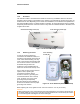

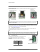
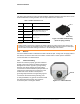
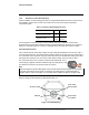
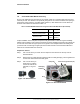
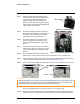
Table Of Contents
- Table of Contents
- Camera Installation
- 1.1 Warnings and Cautions
- 1.2 References
- 1.3 Installation Overview
- 1.4 Camera Connections
- 1.5 Concealed Cable Mount Accessory
- 1.6 Camera Specifications
- Basic Operation and Configuration
- Advanced Configuration

427-0089-00-12 Version 180 August 2020 18
This document does not contain any export-controlled information.
Camera Installation
1.5 Concealed Cable Mount Accessory
Do not route cables through the bottom of the camera unless the concealed cable wall mount (PN
4129742) is used. The wall mount is specifically designed for the camera and allows the opening to
seal properly. When using the concealed cable wall mount, cable dimensions must be within the
minimum and maximum as described in Table 1-4.
Proper installation of the seal plate and panel mount gland seals is critical to long term reliability.
Cables enter the bottom of the camera enclosure through the seal plate and panel mount glands. Be
sure to insert each cable through its panel mount gland on the seal plate before terminating them
(connectors will not fit through the gland). Ensure the manufacturer’s recommended cable bend
radius is not exceeded within the enclosure.
Prepare the Camera
Step 1 Use a 3 mm hex key to loosen the four captive screws and remove the top cover as
described above.
Step 2 Remove the rear cable gland and replace it with the cable gland plug. Use the gasket and
nut that were removed with the cable gland.
Step 3 Use a 3 mm hex key to
loosen the four captive
screws and remove the
seal plate, o-ring, and
plug.
Table 1-4: Cable Min/Max Dimensions using Concealed Cable Wall Mount (PN 4129742)
Cable Min Max
Power (3 conductor),
Ethernet, Accessory cables
4.5 mm
[0.178 in]
10 mm
[0.394 in]
RG 59 Video cable
5.3 mm
[0.209 in]
10 mm
[0.394 in]
Figure 1-13: Seal Plate Removed
Panel mount gland seals (x4)
Seal plate
Gland plug
Plug
installed
Figure 1-14: Removed Parts