
Quick Installation Guide

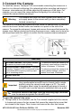


Table Of Contents
- 1 Quick Install Guide
- 1.1 Check Contents
- 1.2 Select a Location
- 1.3 Connect the Camera
- 1.4 Configure for Networking
- 1.5 Mount the Camera
- 1.6 Connect the Camera
- 1.7 Aim the Camera
- 1.8 Check the Boresight
- 1.9 Configure the Analytics
- 1.10 Attach the Camera to a Supported VMS
- 1.11 Camera Dimensions
- 1.12 Register the Product
- 1.13 Contact Information

427-0102-00-28 Triton FH-Series QIG Rev 110
November 2021
This document does not contain any export-controlled information.
Install the mounting hardware for the camera according to the instructions for the
hardware. If relevant, route power, network, and other cables into the mounting
hardware so that they are accessible when the camera is mounted.
Typically, point the camera towards the
ground while ensuring that the field of
view includes as little of the skyline as
possible. Teledyne FLIR recommends
mounting the camera with zero
horizontal rotation; that is, a 0º
installation roll angle. For accurate video
analytics, mount the camera with an
installation roll angle within ±5º.
Attach the camera to the mounting
surface using four 1/4"-20 UNC SUS
19mm screws, each with a metal flat
washer, a spin washer, and a 1/4"-20
UNC nut.
Attaching the Camera to a
Bracket (Example)
6 Connect the Camera
Caution
Carefully following these instructions makes sure water does
not enter the camera and ensures its long-term reliability.
Teledyne FLIR is not responsible for damage to the camera
due to not adhering to these instructions.
Cables enter the camera body through
liquid-tight 3/4" NPT compression
glands, each with a gland seal insert
and plugs for unused holes. To ensure
watertight seals, the cable outer
diameter must be between 0.23"-0.29".
Carefully loosen and remove the gland
nuts.
Remove the appropriate number of
cable gland seal plugs. However, make
sure seal plugs are securely in place for
all unused gland seal holes.
Route the cables through the gland
seals before terminating and connecting
them. Leave the gland nuts loose until
you have finished routing and
connecting all of the cables.
Allow enough space for cable egress
through the gland. The typical cable
bend radius is 50-75mm (2-3").
According to the information in Connect
the Camera, terminate the cables and
then connect them.
Cable Glands (Seal Inserts Not Shown)
Cable Egress Space
(75mm / 3" Bend Radius)