Installation and User Guide Elara™ DX-Series Camera i 427-0300-00-12 - Revision 110 - May 2021 This document does not contain any export-controlled information.
© 2021 FLIR Systems, Inc. All rights reserved worldwide. No parts of this manual, in whole or in part, may be copied, photocopied, translated, or transmitted to any electronic medium or machine readable form without the prior written permission of FLIR Systems, Inc.. Names and marks appearing on the products herein are either registered trademarks or trademarks of FLIR Systems, Inc. and/or its subsidiaries.
Product Registration and Warranty Information Register your Product with FLIR at https://customer.flir.com. For warranty information, see https://www.flir.com/support-center/warranty/security/flir-security-productwarranties/. 427-0300-00-12 - Revision 110 - May 2021 This document does not contain any export-controlled information.
Table of Contents 1. Camera Overview ........................................................................................................................ 1 1.1 Accessing Product Information from the FLIR Website ...................................................... 2 1.2 Camera Dimensions ............................................................................................................ 4 1.3 Camera Specifications ...........................................................................
Table of Contents 4.2 Date & Time Page ............................................................................................................. 42 4.3 Users Page ........................................................................................................................ 43 4.4 Cloud Page ........................................................................................................................ 44 4.5 Audio Page ............................................................
Camera Overview 1 Camera Overview Elara DX-Series cameras include a thermal sensor with digital zoom; a 4K visible light camera with 31x optical zoom; audio; digital I/O; near-infrared (NIR) illumination; laser focus technology (LiDAR); a camera lens window wiper (wash kit available as an optional accessory); and automatic side heat sensors. When the camera is connected to an IP network, it functions as a server, providing services such as camera control, video streaming, and network communications.
Camera Overview Caution Except as described in this manual, do not open the camera for any reason. Damage to the camera can occur as the result of careless handling or electrostatic discharge (ESD). Always handle the camera with care to avoid damage to electrostatic-sensitive components. Prior to making any connections, ensure the power supply or circuit breaker is switched off. Be careful not to leave fingerprints on the camera’s infrared optics.
Camera Overview FLIR Elara DX-Series Product Information Page on FLIR.com 3. Scroll down to see the camera’s specifications and related documents. 4. Click Go to Product Support to open the camera’s support page. FLIR Elara DX-Series Product Support Page 5. Click the Resources tab. 6. Click the relevant Download link to download the resource you need. 427-0300-00-12 - Revision 110 - May 2021 This document does not contain any export-controlled information.
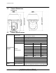
Camera Overview 1.2 Camera Dimensions 1.3 Camera Specifications Array Format DX-3XX models: 320x256 DX-6XX models: 640x512 Sensitivity < 50mK @ 25°C Sensor Technology Long-Life, Uncooled VOx Microbolometer Pixel Pitch 12 µm Frame Rate NTSC: 30 Hz or PAL 25 Hz / 8.3 Hz available Thermal Sensor & Optics Optical Characteristics Video Model Thermal FOV Focal Length DX-350 50° × 38° 4.3 mm DX-324 24° × 18° 9.1 mm DX-312 12° × 9° 18 mm DX-306 6° × 5° 36 mm DX-650 50° × 38° 8.
Camera Overview System Integration Network Pan / Tilt Performance Streaming Resolution Thermal: 640x512 @ 30fps max Visible: Up to 1080p on each stream at 30 FPS each. One 4K stream at 30 FPS, or one 4K stream at 15 FPS and second stream in 1080p at 30 FPS.
Camera Overview Compliance & Certifications Visible Light Camera Cyber Security Humidity 0-95% relative Shock IEC 60068-2-27 Vibe IEC 60068-2-64 Vandalism IK10 except for windows FCC Part 15 (Subpart B, class A); CE Marked; RoHS; WEEE (Waste Electrical and Electronic Equipment Directive), NEMA 4X, ONVIF Profile S, IEC 62368 Sensor Type 4K UHD 1/1.8" Progressive CMOS Lens Field of View HFOV: 61.8° - 2.15° VFOV: 36.65° - 1.2° Focal Length 6.
Installation 2 Installation This camera can be installed outdoors or indoors. For outdoor installation, FLIR recommends: · Always using weatherproof equipment, such as boxes, receptacles, connectors, etc. · For electrical wiring, using the properly rated sheathed cables for conditions to which the cable will be exposed (for example, moisture, heat, UV, physical requirements, etc.). · Planning ahead to determine where to install infrastructure weatherproof equipment.
Installation · Safety: Cables and electrical cords should be routed in a manner that prevents safety hazards, such as from tripping, wire fraying, overheating, etc. Ensure that nothing rests on the unit’s cables or power cords. · Ample Air Circulation: Leave enough space around the unit to allow free air circulation. · Cabling Considerations: Units should be placed in locations that are optimal for the type of video cabling used between the unit and the cameras and external devices.
Installation Connector Connection 2 LAN Attach a Cat 5e or Cat 6 cable from the network switch to the RJ45 LAN connector for a 10/100/1000 Mbps Ethernet and PoE connection. For information about using PoE, see Supplying Power to the Camera. Verify that the LAN connector LEDs are steady green and flashing yellow. 3 AC24V IN If using a 24 VAC power supply, connect its wires to the three-pin power terminal block. See pin assignment below.
Installation Warnings · Make sure the camera’s power cable is properly connected. All electrical work must be performed in accordance with local regulatory requirements. · Use a UL Listed Power Adapter that meets LPS (Limited Power Source) requirements.
Installation 3. While running cables, slightly bend the cables in a Ushaped curve to create a low point. This prevents water from entering the camera along the cables from above. U-Shaped Cable Installation 2.6 Mounting the Camera The following accessories and adapters are available for mounting the camera: · Wall Mount Bracket CX-ARMX-G3 · Corner Adapter CX-CRNR-G3 · Wall Mount Bracket with Power Box CX-ELBX-G3 · Pole Adapter CX-POLE-G3 · Gooseneck Mount with Power Box CX-GSNK-G3 2.6.
Installation Pendant Cap Screw Pendant Cap Screw Holes on Camera 8. Securely tighten the pendant cap screw into the camera. The screw prevents the camera from rotating. 9. Try to rotate the camera and make sure it is not possible to rotate the camera. Warning: If the camera can be rotated, it could become loose and fall. 2.6.2 Wall Mount Bracket CX-ARMX-G3 Wall mount bracket (1.5 inch threaded). Item Wall mount bracket Parts package Quick install guide Details CX-ARMX-G3 No.
Installation Step 1 Step 2 Step 3 Place the smaller, green sponge inside the bracket and route the cables through the center of it, as shown. You might need to cut a slit in the sponge. Place the larger, black sponge inside the bracket, as shown. Route the cables through the pre-cut cross in the sponge. Route the cables through the bracket.
Installation CX-ARMX-G3 dimensions 2.6.3 Wall Mount Bracket with Power Box CX-ELBX-G3 What's in the Box Item Details Wall mount bracket with power CX-ELBX-G3 box Parts package NO. 3 Allen Key NO. 5 Allen Key Sponge Hex Head Cap screw M6 x 20 (stainless steel) Cable gland Quick Install Guide (this document) Qty 1 1 1 1 2 1 1 427-0300-00-12 - Revision 110 - May 2021 This document does not contain any export-controlled information.
Installation Step 1 Step 2 Step 3 Place the sponge inside the bracket and route the cables through the center of it, as shown. You might need to cut a slit in the sponge. Route the cables through the bracket. Follow camera instructions to assemble the pendant cap. Use the Allen key and a hex head cap screw to assemble and firmly affix the camera's pendant cap to the bracket. Step 4 Step 5 Step 6 Affix the power box to the wall or to the column. Attach the bracket to the power box.
Installation 2.6.4 Gooseneck Mount with Power Box CX-GSNK-G3 Gooseneck mount (1.5 inch threaded) with IP68 power box. Item Details Gooseneck bracket and CX-GSNK-G3 box power box CX-GSNK-G3 gooseneck pipe Accessory box No. 2 Allen key No. 3 Allen key No. 5 Allen key No. 6 Allen key M4x8 hex cap double washer Quick install guide Summarized below Qty 1 1 1 1 1 1 2 1 Step 1 Step 2 Step 3 Fix backplate on mounting surface. Assemble power box and tighten screws with No. 6 Allen key.
Installation CX-GSNK-G3 dimensions 2.6.5 Mount Adapters The following mount adapters are available for the camera: · Corner Adapter CX-CRNR-G3 · Pole Adapter CX-POLE-G3 2.6.5.1 Corner Adapter CX-CRNR-G3 90-degree exterior angle corner adapter for CX-xxxx-G3 mounts.
Installation Step 1 Step 2 Step 3 Join parts 1 and 2 together. Tighten hex head cap screws (clockwise). Fix assembled corner adapter to the wall. Step 4 · When using a wall mount bracket (pictured), affix the wall mount bracket onto the corner adapter with washers in the front and screw nuts at the back. · When using a power box, affix the power box onto the corner adapter.
Installation 2.6.5.2 Pole Adapter CX-POLE-G3 Pole adapter for CX-xxxx-G3 mounts, including 2.5-8.5 inch straps. Item Pole mount adapter Accessory bag Quick install guide Details CX-POLE-G3 8.5" ring Stainless streel truss head screw M8*20 Stainless steel truss head screw M8*30 M8 washer M8 screw nut M8 spring washer Summarized below Qty 1 3 4 4 4 4 4 1 Step 2 Step 1 Thread the hoops through the CX-POLE-G3.
Installation 2.7 Initial Configuration You can configure the camera using the DNA tool, the camera's web page, or a VMS. DNA tool Discover camera IP address • Configure IP address, mask, and gateway • Configure DNS settings, MTU, and Ethernet speed Camera's web page • • Change user credentials • Configure more than one camera at the same time • • Notes · The DNA tool does not require a license to use and is a free download from the product's web page on FLIR.com.
Installation In the DNA Discover List, verify that the camera's status is Online. If this is the first time you are configuring the camera or if it is the first time after resetting the camera to its factory defaults, DNA automatically authenticates the camera with the default password for the camera's admin user (admin). If the admin user password has been changed, you need to authenticate the camera. In the DNA Discover List, right-click the camera and select Login.
Installation 2. On the View Settings Home Page, click System Settings, and make sure the Network page appears. 4. Click Static IP addressing and then manually specify the camera's Hostname, IP address, Netmask, and Gateway. You can also specify the DNS Mode, Name Servers, MTU (maximum transmission unit), and Ethernet Speed. 5. Click Save. Applying any changes on the Network page requires reboot the camera. 2.7.
Installation 4. Tighten the delivery joint. 5. Unscrew the knurled nut (01) from the delivery joint (02). Insert the knurled nut on the delivery pipe (03). Insert the end of the delivery pipe into the spinner (04). Lock the nut to the coupling. 6. Fasten the semi-rigid pipe and aim the nozzle towards the camera lens windows. Depending on how and where you are installing the camera and the wash kit, you can use one of the nozzle support brackets supplied with the wash kit to secure and aim the nozzle.
Installation 1. Using the camera's web page, open the Wiper page. 2. Under Washer device installed, click On. To apply the change to this setting, the camera needs to reboot. After the camera reboots, log back in and open the Wiper page. 3. Set the washer position. Click Advanced Settings. Under Washer Position, use the PTZ controls to move the camera into a position so that the washer sprays liquid over both camera lens windows. Click Set.
Operation 3 Operation This chapter includes information about how to access the camera and how to operate it using the View Settings page. 3.1 Accessing the Camera To operate the camera, you first need to access it. You can access the camera by either logging in to the camera's web page. The camera's web page supports Google Chrome® and other popular web browsers. To log in to the camera's web page: 1.
Operation View Settings page for users assigned the admin or expert role Live Video You can select to view visible (V) or thermal (T) live video images. You can also set the Live Video Refresh Rate between 1-30 image frames per second (FPS). The view selected and the Live Video Refresh Rate setting only affect the live video; they do not affect the camera's video streams.
Operation Tips · The zoom functions independently for each camera sensor. For example, zooming in when viewing thermal images does not affect visible images or video streams. · Zooming in and out affects the video streams, unlike the Live Video Refresh Rate setting. System Settings and Other Options Users assigned the admin or expert role can click System Settings to configure the camera. For more information, see the Configuration chapter. Additional choices are for Help and Logout. 3.
Operation The resolution is 640x512 and the Frame Rate range is 5-30 FPS. Codecs, Quality, and Bandwidth The codec used determines which parameters you can set that have a significant impact on the quality and bandwidth requirements of the video stream. Use the default values initially, and then individual parameters can be modified and tested incrementally to determine when bandwidth and quality requirements are met. With the H.
Operation The video streaming uses a protocol generally referred to as RTP, the real-time transport protocol, although there are actually a number of protocols involved, including the Real-Time Streaming Protocol (RTSP). The video stream URLs incorporate the IP address of the camera. Using the camera's default IP address, the complete URLs are: · Visible 1—rtsp://192.168.0.250:554/stream1 · Visible 2—rtsp://192.168.0.250:554/stream2 · Thermal 1—rtsp://192.168.0.
Operation Advanced Settings · Night Mode—Set the visible video to: o Color (day mode) o B/W (night mode) o Auto (default)—Automatically switches the visible video mode according to light level. When Night Mode is set to Auto, you can set the thresholds at which the visible video switches from black and white to color (Night to Day Threshold) and vice versa (Day to Night Threshold).
Operation · Noise reduction settings Noise reduction settings are used to reduce or eliminate artifacts that can limit the ability to positively identify an object. There are two types of noise: luminance and color (chroma) noise. 3D noise reduction and 2D noise reduction settings reduce luminance noise: dots of varying brightness levels (black, white, and gray). It is not recommended to completely eliminate luminance noise, which can result in unnatural images.
Operation o Manual—Allows you to specify a fixed shutter speed, iris size, and gain. Generally used where light levels are fixed and the Full Auto mode does not provide the optimal exposure. This mode is recommended for scenes where there is a fixed lighting contrast and a constant, precise exposure is required; for example, some indoor scenes. § Shutter Speed—Select a fixed shutter speed according to the environmental luminance.
Operation 3.5 Thermal Image Setup - Thermal Page In most installations, it is not necessary to change the default settings of the thermal sensor. However, in some situations, depending on weather, time of day, or scene, modifying one or more parameters can improve the video stream image. Be aware that, when the conditions change, the parameters might need to be adjusted again. It is also a good idea to know how to restore the factory default settings (see Firmware & Info Page).
Operation Defining a custom AGC ROI To change the size of the ROI: Hover over the handle in the bottom-right corner of the ROI, and then click and drag it. To move the entire ROI: Hover over the ROI, and then click and drag it. As soon as you manually change the size of the ROI or move it, the AGC ROI setting automatically changes to Custom. AGC Image Settings In some cases, changing the AGC image settings can provide a better image, depending on personal preferences, display devices, and so on.
Operation Where relevant, changing the settings on the Thermal page immediately affects the live thermal video images and stream. To save changes, click Save. To discard changes, click Reset and then Discard Changes. 3.6 Input/Output (I/O) Page Adjust local and external I/O settings on the I/O page.
Operation 3.7 PTZ Page Use the PTZ page to: · Move the camera left, right, up, or down (pan and tilt) · Define the pan and tilt speed, between 1x-10x · Zoom in and out—click once or click and hold for continuous zoom · Go to the camera's home position · Set the camera's current position as its home position · Define preset positions: a. Under Preset Position, click Set Preset. b. Select a preset index number from 1-128.
Operation · Create and manage a tour of preset positions (only available if presets have been defined): To create a tour, click Create Tour. For each tour stop, click Add, select a preset, and define the amount of time in seconds the tour stops at the preset. You can also move tour stops up or down in the list and delete tour stops. After you create a tour, you can start , pause , stop , edit, or delete it.
Operation 3.8 Illumination Page The camera features NIR illumination for the visible light camera. By default, infrared illumination is set to Auto; when the scene becomes dark enough, the infrared illumination turns on and the visible camera video changes to night mode (black and white video). You can set the night-to-day and day-to-night thresholds on the Visible Page. You can set the infrared illumination to Off. To save a change to the setting as the power-cycle default, click Save. 3.
Operation · Washer device installed—If you have installed an optional wash kit, click On. To apply changes to this setting, the camera needs to reboot. When On is selected, the following washer controls are available: · Washer o Start—Turns the washer on for the amount of time specified for the wash spray duration below. If the camera's pan and tilt is not in the washer position, the camera moves to the washer position. If the washer position has not been defined, define one.
Operation · Installation Height, in meters above the ground (must be greater than zero) · Orientation: the installation angle of the “zero-pan” line of the camera, between 0-360 degrees from North Preset positions are relative to the camera's orientation. Changing the orientation affects existing presets. If any presets have been defined, after changing the camera's orientation, go to the PTZ Page and redefine them. After making any change on the Georeference page, click Save to save the changes.
Configuration 4 Configuration Users assigned the admin or expert role can click System Settings on the View Settings Home Page to configure: · Networking · I/O devices · Date and time · Cybersecurity · User accounts and passwords · ONVIF interface · Audio parameters In addition, users assigned the admin or expert role can access the Firmware & Info page to upgrade the camera's firmware, reset the camera to its factory defaults, reboot the camera, and configure other parameters. 4.
Configuration Caution After changing the camera's IP address, the PC you are using to access the camera's web page might no longer be on the same network as the camera and can no longer access the camera's web page. To access the camera web page again, change the PC's IP address to be on the same network as the camera. When the IP address mode is DHCP, you can set the DNS Mode to DHCP or Static. When the IP address mode is Static, the DNS Mode is also Static.
Configuration When set to Manual, you can copy the local PC's time or specify the hour, minute, second, and date. When set to NTP, you can specify whether the camera obtains the NTP server information from the DHCP server on the network, or manually enter the NTP server information. After setting the date and time parameters, click Save at the bottom of the page. The camera requires a reboot, and a confirmation prompt appears. 4.
Configuration Role Access expert Cannot manage users: · Cannot add/edit/delete users · Cannot change passwords Can access and use all other View Settings and System Settings pages, menus, controls, and settings admin, including the default admin user Can access and use all of the camera's web pages, including adding/editing/deleting users (but cannot delete the default admin user), and setting all passwords All roles can access the camera's video streams, which require authentication.
Configuration 4.5 Audio Page The Audio page provides configuration settings for the camera's audio input and output. The On/Off buttons affect all audio input and output. Turning audio off immediately turns off all camera audio. Audio In When audio is On, the following audio input settings appear: · Encoding—G.711. · Bit Rate—The camera supports an audio input bit rate of 64 kilobits per second (kbps). · Sampling Rate—The camera supports a sample rate of 8 kHz.
Configuration The following settings for the device managing the external I/O connections are available: · Enabled or Disabled · Device IP address and port · Input and output base addresses You can define the number of input and output pins the device manages.
Configuration 4.7 Cyber Page The Cyber page provides security configuration settings for: · Certificates · IEEE 802.1X-compliant communication · Transport Layer Security (TLS) and secure HTTP (HTTPS) communication · Other cybersecurity services Changes to the security configuration settings on the Cyber page do not immediately take effect. To apply changes, click Save and then reboot the camera. 4.7.1 Certificates Before you can enable TLS/HTTPS or 802.
Configuration To generate and install a self-signed certificate for TLS/HTTPS: 1. In the Certificates section and Certification area, select TLS/HTTPS and Self-Signed. 2. Enter information such as country code, city name, and organization name. 3. Click Create Certificate. 4. Allow 15 seconds for the camera to generate the certificate, at which point a confirmation appears. To upload a self-signed or third-party CA signed certificate for TLS/HTTPS or for 802.1X: 1.
Configuration Changing these settings does not immediately take effect. To apply a change to these settings, click Save and then reboot the camera. 4.7.3 TLS/HTTPS Enable or disable camera control using Transport Layer Security (TLS)/secure HTTP (HTTPS). Enable or disable HTTPS redirect. Changes to these settings do not immediately take effect. To apply the changes, click Save and then reboot the camera. 4.7.4 Services Enable or disable digest authentication for the FLIR CGI control interface.
Configuration Changes to Services settings do not immediately take effect. To apply changes to these settings, click Save and then reboot the camera. 4.8 ONVIF Page The ONVIF page provides settings for auxiliary commands and for output actions. To configure the ONVIF interface: 1. Select the number of auxiliary commands (up to seven) and the number of output actions (also up to seven). 2. For each auxiliary command action, specify the ONVIF command name. 3.
Configuration o P&T Start Tour—If a tour is defined on PTZ Page, initiates a tour of pan and tilt preset positions. o P&T Stop Tour—If a tour is defined on PTZ Page, stops the tour of pan and tilt preset positions. 4.
Configuration 3. On your computer or network, browse to and select the firmware file. Caution Only upgrade to firmware developed for Elara DX-Series cameras. 4. Click Upgrade. The camera uploads and installs the firmware, which takes a minute or two. After installing firmware, the camera requires a reboot. When prompted, confirm rebooting the camera. Factory Defaults Click Full Reset to return the camera its original factory configuration.
Maintenance and Troubleshooting Tips 5 Maintenance and Troubleshooting Tips If help is needed during installation, operation, or configuration, contact the local FLIR representative, or visit the FLIR Support Center at: https://support.flir.com/. FLIR Systems, Inc. offers a comprehensive selection of training courses to help get the best performance and value from the thermal imaging camera. Find out more at the FLIR training web page: https://www.flir.com/support-center/training/. 5.
Maintenance and Troubleshooting Tips Performance of Thermal Sensor Varies with Time of Day There may be differences in the way the thermal sensor performs at different times of the day, due to the diurnal cycle of the sun. Recall that the thermal sensor produces an image based on temperature differences. At certain times of the day, such as just before dawn, the objects in the scene may all be roughly the same temperature.
FLIR Systems, Inc. 6769 Hollister Ave Goleta, CA 93117 USA Corporate Headquarters FLIR Systems, Inc. 27700 SW Parkway Ave. Wilsonville, OR 97070 USA Support: https://support.flir.com/ Document: 427-0300-00-12 Revision: 110 Date: May 2021 This document does not contain any export-controlled information.