
User Guide


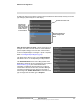


Table Of Contents
- Table of Contents
- Camera Installation
- Basic Operation and Configuration
- Advanced Configuration

427-1065-00-12 Revision 130 November 2019 52
This document does not contain any export-controlled information.
Advanced Configuration
GPIO Input to Snapshot: In the example rule shown at the
right the source type of the alarm is GPIO, with the Input ID
set to 1, which corresponds with the input IO 1 (refer to
Devices Menu GPIO, pg. 47), then takes a snapshot and
stores it locally onboard the camera and/or over the camera
network using FTP or an NAS server.
The Action is set to Capture Image File; a snapshot is
stored when the alarm occurs. The image file can be stored
locally in temporary storage (the default), over the camera
network using FTP (file transfer protocol) or to a network-
attached storage device (NAS). Refer to File Transfer, pg. 43
to configure settings for the FTP, NFS, or Samba transfers.
GPIO Output from Motion Alarm: The final example
shows an alarm rule that causes a GPIO output when a
motion alarm is detected. The source Alarm Id set to 1
corresponds to Region number 1 on the Analytics Setup
page.
Note: the Associated I/O Port is set to 0, and the Associated
I/O Index is set to 2 (corresponding to Input/Output 2).
The GPIO Output State Mode can be set as Bound or
Unbound. If Bound, the output turns on when an alarm
occurs and turns off when the alarm is cleared or the Output
Reset Interval is reached (see Devices Menu GPIO, pg. 47).
If Unbound, the output turns on when an alarm occurs and
remains on until it is reset by the Output Reset Interval time-
out or by a command from the network.
3.2.2 Files Menu
The administrative actions for accessing, updating, and
transferring files are accessed through the Files menu on the
left side of the page. Selected actions from the Firmware,
Configuration, and Log pages are described below.