USER MANUAL Diagnostic Thermal Camera Models TG267, TG297, and TG165–X
USER MANUAL Diagnostic Thermal Camera #NAS100014; r.
Table of contents 1 2 3 4 5 6 7 8 9 Advisories ..........................................................................1 1.1 Copyright .................................................................. 1 1.2 Quality Assurance ...................................................... 1 1.3 Documentation .......................................................... 1 1.4 Disposal of Electronic Waste ......................................... 1 Introduction...................................................
Table of contents 10 11 12 9.3 Reset the Camera..................................................... 25 Specifications................................................................... 26 10.1 Imaging and Optical Specifications ............................... 26 10.2 Detector Specifications .............................................. 26 10.3 Image Presentation Specifications................................ 26 10.4 Measurement Specifications ....................................... 27 10.
1 Advisories 1.1 Copyright ©2020 FLIR Systems, Inc. All rights reserved worldwide. No parts of the software including source code may be reproduced, transmitted, transcribed or translated into any language or computer language in any form or by any means, electronic, magnetic, optical, manual or otherwise, without the prior written permission of FLIR Systems.
2 Introduction The FLIR TG267, TG297, and TG165–X are Diagnostic Thermal Cameras which combine non-contact temperature measurement and thermal imaging into one troubleshooting tool to help you quickly find the source of heat-related problems and spot potential faults. The FLIR TG267 adds Type-K thermocouple contact temperature measurements. The FLIR TG297 offers a high temperature range to 1030℃ (1886℉). Visit https://support.flir.
3 Safety 3.1 Safety Warnings and Cautions WARNING ⚠This symbol, adjacent to another symbol indicates the user must refer to the manual for further information. WARNING The instrument’s IP54 rating is only in affect when the top flap (covering the USB-C and Thermocouple jacks) is completely sealed. Do not operate the instrument with the flap open, except for charging, PC interface, or Type-K thermocouple use.
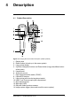
4 Description 4.1 Product Description Figure 4.1 Imaging IR Thermometer Description (TG297 pictured) 1. 2. 3. 4. Display area Return button (to back up in the menu system) Laser pointer button Up/Down Navigation buttons and Power button (long press)/Menu button (short press) 5. Lanyard post 6. Accessory mount 7. High temperature filter switch (TG297) 8. Lepton® IR camera 9. Laser pointer with circular target-spot assist 10. USB-C and Thermocouple jack compartment 11. Spot thermal sensor 12.
4 Description 4.2 Control Button Descriptions Long press to power ON or OFF Short press to access the menu system Return button. Back out to previous screen in menus Press to scroll upward in the menus Press to scroll downward in the menus Press to activate the Laser pointer TRIGGER Pull trigger to capture camera image Pull trigger to exit the menu system 4.3 Display Description Figure 4.2 Display Description 1. 2. 3. 4. 5. 6.
4 Description 7. Camera image area 8. Center spot cross-hairs 9. Laser Pointer active 10. Center spot temperature measurement 11. Thermocouple measurement (TG267) #NAS100014; r.
5 Operation 5.1 Camera Power Power is supplied by a rechargeable lithium battery. Long press the power button (center) to switch the camera ON or OFF. If the camera does not power ON, charge the battery by connecting to an AC wall charger using the supplied USB-C cable. The USB-C jack is located in the top compartment. Do not use the camera while it is charging. When the top flap is closed, the camera is rated IP54 for encapsulation. See Section 9.
5 Operation 4. Use the Laser pointer to accurately target a spot. Press the Laser pointer button to switch ON the Laser pointer. The camera’s Laser pointer includes a circular spot indicating the area that is being monitored for temperature, utilizing DOE (Diffractive Optical Elements) technology. See the Laser pointer image example below in Figure 5.2. If the Laser beam does not appear when the button is pressed, check the menu system (under Device Settings) to ensure that the Laser is enabled. 5.
5 Operation 3. When engaged, the high end of the temperature range (>752℉ [400℃ ]) is accessible. 5.4 Type-K Thermocouple Measurements (TG267) WARNING Note the temperature range limit printed on the thermocouple connector (or verify the range with the manufacturer).
5 Operation Figure 5.4 Thermocouple temperature readout (33.7℃, in this example) 1. If necessary, enable the thermocouple mode in the menu system (under Measurement). The thermocouple is enabled when the ‘TC’ label is shown on the display. 2. Connect a Type-K thermocouple sub-miniature plug (see Figure 5.3) to the jack in the top compartment. 3. Touch the thermocouple probe tip to the surface under test or hold it in air. Read the temperature value on the display next to the ‘TC’ label, see Figure 5–4.
5 Operation 5.5 Visible Spectrum Camera Figure 5.5 Visible Spectrum Digital Camera Image 1. Long press the power button to switch the camera ON. 2. Select the Visible Image mode in the menu system (under Image Adjustments/Image Mode). 3. Point the camera toward the test area and scan as desired. 4. View the image on the display, see Figure 5–5. Pull the image capture trigger to save an image. Refer to Section 5.6, Capturing and Working with Images, (next) for more information. 5.
6 Programming Menu System 6.1 Menu System Basics Short press the MENU button to access the menu system. Use the MENU button to switch settings ON or OFF, use the Return button to move to the previous screen, and use the arrows to scroll. The MENU button is used in some cases to confirm settings. Use the trigger to exit the menu system. 6.2 Main Menu • LIGHT: Short press MENU to switch the Work light ON or OFF. • GALLERY: Press MENU to access the stored images.
6 Programming Menu System 1. Image Modes: Press MENU at IMAGE MODES and use the arrow buttons to select VISIBLE IMAGE or THERMAL PLUS VISIBLE IMAGE (MSX®). 2. MSX® Alignment: Adjust the alignment (so that the thermal image and the visible image line up accurately) as follows: While viewing the THERMAL PLUS VISIBLE IMAGE screen in the menu, press MENU to access the MSX® adjustment screen and then use the arrow buttons to adjust the alignment. Press MENU to confirm.
6 Programming Menu System 3. Colors: Press MENU at the colors menu and use the arrow buttons to select a color palette: Iron, Rainbow, White hot, Black hot, Arctic, or Lava. Press MENU to confirm selection. • SETTINGS: Press MENU to access the Settings sub-menu (see below): 6.3 Settings Sub-Menu • MEASUREMENT #NAS100014; r.
6 Programming Menu System 1. Center Spot: Press MENU to enable/disable the display cross-hairs. The cross-hairs should be used as a reference only to identify the spot that is being measured for temperature. Use the Laser pointer for more accurate targeting. 2. Emissivity: Press MENU to open the Emissivity adjustment utility. Use the arrows to scroll through the presets (0.95, 0.80, and 0.60) and use the MENU button to select a preset.
6 Programming Menu System • DEVICE SETTINGS 1. Bluetooth® (TG267 and TG297 only): Press MENU to switch Bluetooth® ON or OFF. See Section 7, Bluetooth® Communication and FLIR Tools™, for details. 2. Laser: Press MENU to enable/disable the Laser pointer. When enabled, you can use the Laser pointer button to switch ON the Laser pointer. Use the Laser pointer for accurate targeting of measurement spots. 3. Screen brightness: Use the arrows to select the desired display intensity (LOW, MEDIUM, or HIGH).
6 Programming Menu System 4. Auto Power OFF (APO): Use the arrows to scroll and MENU to select the desired APO time (5/15/30 minutes). Set to ‘Never’ to disable APO. • GENERAL SETTINGS 1. Temperature Unit: Use the arrows and the MENU button to select °C or °F. 2. Time & Date: Use the arrows to scroll and the MENU button to set the Time, Date, Time Format, and Date Format. #NAS100014; r.
6 Programming Menu System 3. Language: Use the arrows to scroll and the MENU button to select a language. 4. System Info: Scroll to desired topic: Model Number, Serial Number, Software Level, Revision, Battery status (%), and remaining Internal Storage Capacity. • GENERAL SYSTEM INFO: Press MENU to view compliance information. #NAS100014; r.
6 Programming Menu System • FACTORY RESET: Follow the prompts to reset the User Settings back to Factory Default status. #NAS100014; r.
7 Bluetooth® Communication and FLIR Tools™ 7.1 Bluetooth® Communication Overview When paired with a mobile device running the FLIR Tools™ App (using the METERLiNK® protocol), the TG267 and TG297 continually transmit readings for live display on the mobile device. You can also send images, stored on the camera, to your mobile device. 7.2 Download the FLIR Tools™ Mobile App Download the mobile App from the Google Play™ store, the Apple App store, or from this link: https://www.flir.
7 Bluetooth® Communication and FLIR Tools™ Figure 7.1 Pairing the camera with a Mobile Device Figure 7.2 Sending Images to a Mobile Device #NAS100014; r.
7 Bluetooth® Communication and FLIR Tools™ Figure 7.3 Viewing Transferred Images on a Mobile Device 7.5 FCC Compliance This device complies with part 15 of the FCC Rules. Operation is subject to the following two conditions: 1. This device may not cause harmful interference. 2. This device must accept any interference received, including interference that may cause undesired operation.
7 Bluetooth® Communication and FLIR Tools™ 4. Consult the dealer or an experienced radio/TV technician for help. WARNING Changes or modifications not expressly approved by the party responsible for compliance could void the user’s authority to operate the equipment. 7.6 GITEKI Certified This product is GITEKI certified. The GITEKI mark is displayed in the System Information menu, see the Settings Sub-menu section. #NAS100014; r.
8 Field Firmware Updates The camera includes a USB-C port in the top compartment. The USB port allows you to update the System firmware by first downloading an update file from the FLIR website and then transferring the file to the camera via USB. Connect to a PC using a USB-C cable. Firmware updates are available from https://support.flir.com. NOTE This camera is not 100% compatible with USB-C to USB-C cables. Use only USB-C to USBA cables. The supplied cable is USB-C to USB-A type.
9 Maintenance 9.1 Cleaning Wipe the housing with a damp cloth as needed. Do not use abrasives or solvents. Clean the lenses with a high-quality lens cleaner. 9.2 Battery Considerations and Service The rechargeable lithium battery is not user-serviceable. Please contact FLIR support for service instructions: https://support.flir.com. For best results, charge the battery immediately after seeing a low battery indication using the supplied USB-C cable (with an AC wall charger, not supplied).
10 Specifications 10.1 Imaging and Optical Specifications IR resolution TG267 and TG297: 160 x 120 pixels TG165–X: 80 x 60 pixels Digital image enhancement Included Thermal Sensitivity /NETD < 70 mK Field of View (FOV) TG267 and TG297: 57° (H) x 44° (D) Minimum focus distance 0.89 ft. (0.
10 Specifications Image adjustment Automatic Image modes • • Thermal MSX® (Multi-Spectral Dynamic Imaging) Visible Spectrum 10.4 Measurement Specifications Object temperature range TG267: –25 ~ +380℃ (–13 ~ +716℉) TG297: –25 ~ +1030℃ (–13 ~ +1886℉) TG165–X: –25 ~ +300℃ (–13 ~ +572℉) Accuracy at ambient temperature: 59 ~95℉ (15 ~ 35℃) -13℉ ~ 32℉ (-25℃ to 0℃): ± 7.0℉ (± 3.0℃) 32℉ ~ 122℉ (0℃ ~ 50℃): ± 5.0℉ (±2.5℃) 122℉ ~ 212℉ (50℃ ~ 100℃): ± 3.0℉ (± 1.5℃) 212℉ ~ 932℉ (100℃ ~ 500℃): ± 2.
10 Specifications Type-K Temperature Resolution 0.1℉ (0.1℃) Type-K Temperature Accuracy ± (1% of reading + 5.4℉ [3℃]) Maximum voltage at Type-K input 60V DC or 24V AC rms 1. Note that this is the temperature range of the camera NOT the range for the supplied thermocouple. Please do not exceed the specified range printed on the thermocouple label. To measure higher or lower than the range of the supplied thermocouple, please use a Type-K thermocouple rated for the desired range.
10 Specifications Rated power 0.5 W Light output 100 Lumens 10.11 Laser Pointer Specifications Laser type DOE (Diffractive optical elements) Laser function Indicates the size of the measurement area (circular target) Laser class Class I 10.12 Data Communication and Interface Specifications Interfaces USB 2.0 and Bluetooth® (TG267 and TG297 only) USB USB-C for data transfer and battery charging Not 100% compatible with USB-C to USBC cables. Use only a USB-C to USB-A cable.
10 Specifications 10.14 Environmental Specifications Altitude 6562 ft. (2000 m) Pollution degree 2 Operating temperature 14 ~ 113℉ (-10 ~ 45℃) Storage temperature -22 ~ 131℉ (-30 ~ 55℃) Humidity (operating and storage) 0 ~ 90% Relative Humidity (RH) 32 ~ 98.6℉ (0 ~ 37℃) 0 ~ 65% RH 98.6 ~ 113℉ (37 ~ 45℃) 0 ~ 45% RH 113 ~ 131℉ (45 ~ 55℃) EMC EN 61000–6–3 EN 61000–6–2 FCC 47 CFR Part 15 Class B Magnetic fields EN 61000–4–8 Class 3 Radio spectrum ETSI EN 300 328 FCC Part 15.
10 Specifications 10.15 Physical Specifications Weight 13.9 oz. (0.39 kg) Size (L x W x H) 8.3 x 2.5 x 3.2 in. (210 x 64 x 81 mm) Accessory mount UNC ¼”-20 10.16 Included Equipment Standard equipment Camera, USB-C cable, printed Quick Start Guide, Lanyard, Carry Pouch #NAS100014; r.
11 2–10 Extended Warranty To activate the extended 2–10 warranty, please register your product within 60 days of purchase. Otherwise, the standard one-year warranty will be in affect from date of purchase. The 2–10 warranty covers parts and labor for the camera for 2 years and coverage of the detector for 10 years. Register your product at https://support.flir.com/prodreg. #NAS100014; r.
12 Customer Support Repair, Calibration, and Technical Support: https://support.flir.com. 12.1 Corporate Headquarters FLIR Systems, Inc. 27700 SW Parkway Avenue Wilsonville, OR 97070, USA #NAS100014; r.
#NAS100014; r.
Website last page http://www.flir.com Customer support http://support.flir.com Copyright © 2020, FLIR Systems, Inc. All rights reserved worldwide. Disclaimer Specifications subject to change without further notice. Models and accessories subject to regional market considerations. License procedures may apply. Products described herein may be subject to US Export Regulations. Please refer to exportquestions@flir.com with any questions. Publ. No.