
Quick Connect Guide

427-0089-00-28 Rev 120 July 2016
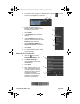
Step 1 Remove cover: Using 3 mm hex key, loosen four captive
screws. Access screws through slots in sunshield.
Removing the sunshield is not necessary.
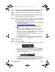
Step 2 Install cables through sealing gland:
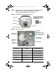
Step 3 Ter m i n a te ca b l e s :
Connection Purpose
Cable dimensions
required for sealing
BNC Analog video
5.3 mm (0.209 in) minimum;
6.2 mm (0.244 in) maximum
3-pin Terminal Power, Vac or Vdc
4.5 mm (0.178 in) minimum;
5.2 mm (0.205 in) maximum
Ethernet
PoE power, communications,
IP video stream
4.5 mm (0.178 in) minimum;
5.2 mm (0.205 in) maximum
6-pin terminal J5 General purpose I/O (GPIO)
4.5 mm (0.178 in) minimum;
5.2 mm (0.205 in) maximum
6-pin terminal J3
(reserved for future use)
Do not connect
Video coax
Gland nut
Ground
Power cable
Ethernet
Accessory
Fill any unused hole with
orange plug. Re-tighten
gland nut after installation
is completed.
microSD card
(not supplied)
Reserved for
6-pin GPIO
terminal
Chassis ground (PE)
Vdc – or Vac (neutral)
Vdc + or Vac (line)
future use
Pin 1
Ethernet port
3-pin power
terminal
BNC
analog video
427-0089-00-28 v120 FC-Series Quick Connect.fm Page 2 Thursday, July 7, 2016 7:38 AM