Installation Manual FC-Series FC-Series O FC-Series ID 427-0089-00-12 Version 160 March 2019 This document does not contain any export-controlled information.
© 2019 FLIR Systems, Inc. All rights reserved worldwide. No parts of this manual, in whole or in part, may be copied, photocopied, translated, or transmitted to any electronic medium or machine readable form without the prior written permission of FLIR Systems, Inc. Names and marks appearing on the products herein are either registered trademarks or trademarks of FLIR Systems, Inc. and/or its subsidiaries.
Table of Contents Table of Contents Camera Installation 1.1 Warnings and Cautions ............................................................................................... 5 1.2 References .................................................................................................................. 5 1.3 Installation Overview ................................................................................................... 6 1.3.1 Camera Connection Options .......................................
Table of Contents Advanced Configuration 3.1 Setup Menu ............................................................................................................... 42 3.1.1 Temperature Page ............................................................................................ 43 3.1.2 Video Setup ...................................................................................................... 44 3.1.3 Thermal Image Setup .......................................................................
1 Camera Installation This manual describes the installation and initial configuration of the FC-Series thermal camera. The FC-Series ID and the FC-Series O are based on identical hardware. The FC-Series ID camera has software installed providing for on-board video analytics: setting of detection regions, trip lines, and classification of detected objects. Refer to Video Analytics Setup—FC-Series ID only, pg. 49.
Camera Installation 1.3 Installation Overview The FC-Series camera is an infrared thermal imaging camera intended for outdoor security applications, and can be installed in a fixed location or on a pan/tilt mechanism. The camera is intended to be mounted on a medium-duty fixed pedestal mount or wall mount commonly used in the security industry. The camera mount must support up to 5.4 lbs (2.5 kg).
Camera Installation PoE+ Power Supplies With PoE+, camera power is delivered to the camera over the Ethernet cable via the camera’s standard RJ-45 Ethernet connector. The FC-Series camera is a Powered Device compliant with the IEEE 802.3at-2009 standard, known as PoE+ or PoE Plus. The FC-Series camera is also backward compatible with the older IEEE 802.3af-2003 standard. When connected to Power Sourcing Equipment compliant with the earlier, lower power IEEE 802.
Camera Installation • Pole Mount Adapter Kit (PN 4132982) - Adapter kit that allows the Concealed Cable Wall Mount to be mounted to a pole (75 mm [3 in] min to 180 mm [7 in]; larger pole diameter requires use of customer supplied band clamps) • FC-Series De-Ice Kit (PN 421-0056-00 for 60 mm lens, and PN 421-0057-00 for 75 mm lens) The 60 mm and 75 mm lenses are not thermally conductive.
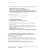
Camera Installation supported by FLIR IP cameras. Because these systems tend to evolve and change over time, contact the local FLIR representative or FLIR Technical Support for information. α Camera mounted upright For installations with multiple FC-Series ID cameras with on-board video analytics, the fields of view of cameras should overlap in order to remove all dead zones in which a camera cannot see a target “head to toe”. The camera’s on-board analytics must be calibrated to detect targets.
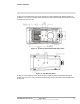
Camera Installation If using two 1/4-20 fasteners in the center of base, the maximum depth of the fastener should not exceed 12.5 mm (0.5 in). If using four M5 x 0.8 fasteners, the maximum depth of the fastener should not exceed 10.0 mm (0.4 in). Figure 1-1: FC-Series Camera Bottom Mounting Holes Figure 1-2: Top Mounting Holes If using two 1/4-20 fasteners in the center of top, the maximum depth of the fastener should not exceed 12.5 mm (0.5 in).
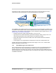
Camera Installation As the diagram below indicates, be sure to allow adequate space for cable egress behind the gland. This requirement may vary, depending on the installation. Maintain the bend radius per the recommendation of the cable manufacturer. The typical cable bend radius is 50-75 mm (2-3 in). Figure 1-3: Rear Cable Bend Radius 1.3.7 Camera Mounting with Concealed Cable Wall Mount The FC-Series camera can be secured to the optional Concealed Cable Wall Mount with four M5 x 0.
Camera Installation 1.3.8 Sunshield The camera includes a sunshield which should be used for any installation where the camera is exposed to direct sunlight or precipitation, If the camera is mounted with the top mounting holes, the sunshield is not used. Depending on the needs of the installation, the sunshield can be positioned in the neutral (middle) position, or slightly forward or rearward.
Camera Installation 1.4 Camera Connections Figure 1-7: Camera Connections Refer to Table 1-1 for a description of these camera connections. Table 1-1: FC-Series Camera Connections Connection 1.4.
Camera Installation customer supplied microSD card (up to 64 GB) is installed, local storage is persistent through reboots and power cycles. Pull back cage to unlock Close cage, press down and push forward to lock Insert microSD card Lift edge to open 1.4.2 Bench Testing Note If the camera is to be mounted on a pole or tower or other hard-to-reach location, it may be a good idea to connect and operate the camera as a bench test at ground level prior to mounting the camera in its final location.
Camera Installation The power cable supplied by the installer must use wires that are sufficient size gauge for the supply voltage and length of the cable run to ensure adequate current carrying capacity (18 AWG recommended for most installations). Always follow local building/safety codes. Strip ends 3 Places (0.2±.04 in) 6.0±1 mm Remove outer jacket (0.8±.20 in) 20.0±5 mm Power Cable Note The terminal connector for power connections will accept 16 AWG to 24 AWG wire size.
Camera Installation The spring-cage and pierce contact accepts 22 AWG to 24 AWG, stranded conductors with a 1.6 mm maximum diameter including insulation. Do not strip insulation from conductors. Table 1-3: GPIO Connections - J5 Pin Connection 1 Chassis ground 2 GPIO Out 3 GPIO Out 4 GPIO In2 (Digital ground) 5 GPIO In1 (+5V) 6 Chassis ground Notes Pin 1 When the camera sends an output signal, an external voltage on one pin is applied to the other pin.
Camera Installation 1.4.8 Rear Access Cable Gland Sealing Proper installation of cable sealing gland and use of appropriate elastomer inserts is critical to long term reliability. Cables enter the rear of the camera mount enclosure through a liquid-tight compression gland. Table 1-3: Rear Exit Cable Min/Max Dimensions Cable Min Max Power (3 conductor), Ethernet, Accessory cables 4.5 mm [0.178 in] 5.2 mm [0.205 in] RG 59 Video cable 5.3 mm [0.209 in] 6.2 mm [0.
Camera Installation 1.5 Concealed Cable Mount Accessory Do not route cables through the bottom of the camera unless the concealed cable wall mount (PN 4129742) is used. The wall mount is specifically designed for the camera and allows the opening to seal properly. When using the concealed cable wall mount, cable dimensions must be within the minimum and maximum as described in Table 1-4.
Camera Installation Step 4 Install the wall mount (PN 4129742) to the wall and pull the cable(s) through the mount. Cut a small cross-slit in the black mount gasket and push the cable(s) through the gasket. Pull the cable(s) through the opening in the bottom of the camera. A single Ethernet cable is shown in the images. Mount Gasket Figure 1-15: Camera Mount Step 5 Secure the camera to the mount using four M5 x 0.8 threaded fasteners to the bottom of the camera.
Camera Installation 1.6 Camera specifications Array Format Detector Type Thermal Camera Effective Resolution Spectral Range 640 x 512, 336 x 256 (17 µm pixel pitch) 320 x 256 (34 µm pixel pitch) Long-Life, Uncooled VOx Microbolometer 640 x 512: 327,680 336 x 256: 86,016 320 x 256: 81,920 7.5 to 13.5 µm Lens Athermalized, focus-free E-zoom Continuous to 4x Field Of View (Focal Length) for available 640 x 512 camera lens configurations. FC-690 90° × 69° (7.
Camera Installation 4.55 lb (2068 g) with sun shield (7.5 mm, 9 mm, 13 mm, 19 mm, 25 mm, 35 mm) 5.20 lb (2364 g) with sun shield (60 mm) 5.65 lb (2568 g) with sun shield (75 mm) Weight 9.2" x 4.6" x 4.1" without sun shield, (234 mm x 117 mm x 104 mm) 11.5" x 5.1" x 4.6" with sun shield, (292 mm x 130 mm x 117 mm) Dimensions (L,W,H) General Purpose Input/ Output (GPIO) One input dry alarm contact; One output relay contact (rated load 0.
2 Basic Operation and Configuration This chapter provides basic information on how to operate the FC-Series camera. A bench test can be used to verify camera operation before the camera is configured for the local network. This chapter also provides general configuration information. 2.1 IP Camera, ONVIF Profile S Compliant When connected to the network the camera functions as a server; providing services such as camera control, video streaming, network communications, and geo-referencing capabilities.
Basic Operation and Configuration Step 3 From the PC connected to the camera network, use the DNA utility to discover and display the camera’s current IP address. a Download the DNA utility. b c Unzip the utility, then double-click to run the executable file ( DNA.exe). All the units on the VLAN are discovered. For additional instructions on using DNA, refer to the DNA User’s Manual available in the Help ( ) link while the software is running.
Basic Operation and Configuration appear. A pull-down list in the upper right allows the user to select a language option. Enter user for the User Name and user for the Password, and click Log in. Figure 2-1: Camera Web Page Login Screen 2.3.2 Live Video Page The Live Video page displays a live image from the camera on the left part of the screen and at the top of the screen menu choices: including Live Video (the red text indicates it is selected), Help, and Log out.
Basic Operation and Configuration In the lower right of the web page there is a frame rate selector. This selector allows the user to change the rate at which the frames are displayed in the browser from the default 8 fps up to 16 fps. This rate controls the user’s own web browser only, and does not affect the video streams to other users or to an NVR. For slow communication links, if there is a problem displaying the video image, it may help to slow down the frame rate.
Basic Operation and Configuration The following buttons appear for the FC-Series cameras: Digital Zoom—FC-Series O only These buttons zoom the camera video. The zoom state (and other camera settings) can be saved in the IR Setup page (refer to Save Settings, pg. 49). This will allow the camera to retain the desired zoom state (field of view) after the power is cycled. Note Changes to the zoom settings require all Analytic detection regions and calibrations to be updated.
Basic Operation and Configuration Analytics On/Off—FC-Series ID only The FC-Series ID camera Intrusion Detection Analytics can be enabled or disabled from the Live Video page. Detection area and tripwire alarms must be setup prior to use. Refer to Video Analytics Setup—FC-Series ID only, pg. 49. De-Ice On/Off—Configuration dependent This button manually turns the lens heater on or off.
Basic Operation and Configuration 2.4.2 Server Menu When a user logs in as expert or admin, the Maintenance Server menus are available. When the Server menu is selected, the LAN Settings page appears. The basic camera configuration steps are accessed through the Maintenance Server menu, using the menus on the left side of the page. The LAN Settings, Services, and Security Options selections are described below. The expert login has access to these Server pages, but can not change passwords.
Basic Operation and Configuration When the IP address is changed and the Save button is clicked, a pop-up message will appear to indicate the network interface must be restarted. Once the IP address of the camera is changed, the PC may no longer be on the same network and therefore may not be able to access the camera until the IP address on the PC is changed also. For that reason, it makes sense to change the IP address after making other configuration changes. IEEE 802.1X Security: The 802.
Basic Operation and Configuration Step 6 Use the Browse and Upload buttons to upload the Client Certificate from the server provided by the network administrator. Step 7 Using the Browse and Upload buttons, upload the Private Key and Private Key Password associated with the identity. The Private Key Password field can be left blank if a password is not required. If uploading a PKCS #8 file, the private key must be a valid PKCS #8 file.
Basic Operation and Configuration If the Custom mode is selected, a pop-up window allows the information to be entered manually. Note The Nexus server must be stopped before making changes to the date and time settings. Set the date and time parameters, then select the Save button at the bottom of the page. After saving the settings, reboot the system. Refer to Server Status, pg. 35. Msg Systems: Use the Msg Systems page to setup a connection to a mail server to send outgoing email notifications.
Basic Operation and Configuration Notification Lists: Use this page to setup multiple email addresses and other notifications that can be sent as a result of alarms being processed by the Alarm Manager. TLS Config: The settings on this page enable secure, encrypted communication between clients and the camera; for example, when your web browser accesses the camera’s web interface. Note The camera also supports TLS authentication over the camera’s LAN.
Basic Operation and Configuration private and public key files. If the certificate was signed by a third-party CA, you can download the CA Certificate and the private and public key files. To generate and install a self-signed certificate: Step 1 Under Generate Certificate, for Method, select Self-Signed. Step 1 Enter information such as country code, city name, and organization name. Step 2 Scroll to the bottom of the page and click Generate Certificate.
Basic Operation and Configuration To upload a self-signed or third-party CA signed certificate: Step 1 For Method, select Upload Certificates. Step 2 If you are uploading a self-signed certificate, under Upload Certificate, browse for and upload the public key file. Then, under Private Key, browse for and upload the private key file. If you are uploading a third-party CA signed certificate, under Upload Certificate, browse for and upload the public key file.
Basic Operation and Configuration Server Status: The Server Status page provides an indication of the current server status (either running or stopped) and buttons for starting or stopping the server or for rebooting the system. Toggle Server (Stop/Start) After making configuration changes, it is necessary to save the changes to the server (there is a Save button at the bottom of each configuration page). The configuration changes do not take effect immediately.
Basic Operation and Configuration • Enabling the camera’s firewall and enabling or disabling specific services and their ports • Enabling Nexus CGI digest authentication Restrict web configuration Add IP address The admin login can limit which computers have access to the web browser interface. Simply add a computer’s IP address and click Add. After all the allowed IP addresses are entered, select the Save button to save the changes.
Basic Operation and Configuration Note A VMS Remote to the camera, ONVIF, or Nexus CGI, uses the same password as the web interface. Refer to VMS Remote, pg. 57. Firewall settings For enhanced security, a firewall can be enabled (by scrolling down on the Security Options page).
Basic Operation and Configuration The thermal camera, on the other hand, detects energy that is directly radiated from objects in the scene. Most objects in typical surroundings are not hot enough to radiate visible light, but they easily radiate energy in the portion of the infrared spectrum that the camera can detect, the long wave infrared (LWIR). Even very cold objects, like ice and snow, radiate this type of energy.
Basic Operation and Configuration Use the following procedure and solvents, as required: • Acetone – removal of grease • Ethanol – removal of fingerprints and other contaminants • Alcohol – final cleaning (before use) Step 1 Immerse lens tissue (optical grade) in Alcohol, Acetone, or Ethanol (reagent grade). Step 2 With a new tissue each time, wipe the lens in an “S” motion (so that each area of the lens will not be wiped more than once). Step 3 Repeat until the lens is clean.
Basic Operation and Configuration If necessary, test to make sure the video from the camera can be viewed by a generic video player such as VLC media player (http://www.videolan.org/vlc/). To view the video stream, specify RTSP port 554 and the appropriate stream name. For example: rtsp://192.168.250.116:554/ch0, and rtsp://192.168.250.116:554/ch1 Port 554 is the standard RTSP port as well as the default for the camera.
Basic Operation and Configuration Image too dark or too light By default the FC-Series camera uses an Automatic Gain Control (AGC) setting that has proven to be superior for most applications, and the camera will respond to varying conditions automatically. The installer should keep in mind that the sky is quite cold and can strongly affect the overall image.
3 Advanced Configuration In this chapter, additional setup and configuration settings related to the following topics are described: • • • • • • Setting up the video streams to optimize quality and network performance Optimizing the thermal image Setting up detection areas for Analytics Configuring alarm responses and email notifications Configuring the camera to work with a third-party VMS (ONVIF) Enabling On-Screen Display (OSD) text When configuration changes are made with the web browser, the settin
Advanced Configuration 3.1.1 Temperature Page The Temperature Info page displays temperature readings from the camera and GPIO signal status. Thermo Summary Select the temperature units to display: Kelvin, degree Celsius, or degree Fahrenheit.
Advanced Configuration 3.1.2 Video Setup Video: By default, two video streams are enabled for the camera: Video 0 and Video 1. Both video streams are available for viewing from a client program such as FLIR Latitude, a stand-alone video player, or a third-party VMS (including ONVIF systems). By default, Video 0 uses MJPEG encoding and Video 1 uses H.264 encoding. To modify parameters that affect a particular IP Video stream from the camera, select the appropriate link (for example, Video - 0).
Advanced Configuration Caution! Adjustments to these settings should only be made by someone trained with thermal cameras and a thorough understanding of how the various settings affect the image. Haphazard changes can lead to image problems including a complete loss of video. The parameters in the Encoding section will have a significant impact on the quality and bandwidth requirements of the video stream.
Advanced Configuration For enhanced security, RTSP authentication can be enabled. By default, the video streams from the camera are sent using unicast packets rather than multicast. This means a given packet of IP Video will be sent separately to each client that has that video stream open. Therefore each additional client will cause the bandwidth to increase and cause more overhead on the system in comparison to multicast.
Advanced Configuration The default value for the stream from VIDEO - 0 is ch0. For example, the complete connection string is: rtsp://192.168.250.116/ch0. This stream name can be used to open a video stream with a thirdparty video player. By default the video stream uses the IP address of the camera. 3.1.3 Thermal Image Setup In most installations it will not be necessary to change the thermal camera from the default settings.
Advanced Configuration AGC ROI: The AGC Region Of Interest (ROI) determines what portion of the image is used in the calculation of the AGC. By default all of the pixels in the image are considered (Full Screen); in some cases it may be possible to improve the contrast if a portion of the image is excluded. For example, if the field of view includes a portion of the sky, typically quite cold, it may be desirable to restrict the ROI to the portion of the image below the horizon.
Advanced Configuration Misc. (Lookup Table): Each Look Up Table (LUT) provides a different display of the various detected levels of thermal energy as either colors or gray-scale values. Look Up Table 1 is white hot and Look Up Table 2 is black hot; the other tables assign different colors to different temperatures. These color palettes can also be selected from the Live Video page (refer to Toggle Palette, pg. 26).
Advanced Configuration tripwires. Each area/tripwire is assigned an Alarm ID number (1 to 8) based on the order in which they are created and the available IDs. If an area is deleted, its Alarm Id will be available for reuse. Calibration progress Add Areas Global Settings Calibration Tools Figure 3-1: Analytics Page Analytics Calibration • The camera must be mounted in its final location in order to calibrate the scene in the field of view using either the auto or manual calibration tool.
Advanced Configuration Step 2 To automatically calibrate detection settings, from the Calibration Mode drop-down list, select Auto. Step 3 Click Relearn. The camera automatically calibrates the depth of the FoV based on people walking in the scene. Be sure that people are walking along the entire vertical axis of the FoV until calibration is finished. The On-Screen Display shows the progress as a percentage in the upper left corner of the video (see Figure 3-1).
Advanced Configuration Global Settings Click the settings icon Global Settings. below the image to access There are three settings for sensitivity which control the threshold for detection (as well as false alarms): Low, Medium, and High. When set to low, the analytics will detect fewer objects (also fewer false alarms) than when set to high. Set Show Regions to Yes to show any detection areas as black boxes and tripwires as black lines in the video.
Advanced Configuration Creating Analytics Regions Selected Region (Alarm Id 3) Select Direction Select targets Set dependency Manual Selection Save Add Region Analytics On/Off To create a detection area, click the add region icon and a new four corner area will appear on the image. Drag any of the highlighted circles to expand and define the detection area.
Advanced Configuration Check Calibration 1. Click the icon and set Analytics Enabled to Yes. 2. Set Show Tracking to Classified Boxes or Show Triggered, then check the Lines box. 2 3. Click Save. 3 4. Have subjects (person, car, truck, etc) enter the area or cross the tripwire at various distances from the camera. The boxes should be classified correctly and the direction across tripwires should be as expected. The image below shows a classified human box and tracking line in a detection region.
Advanced Configuration 3.2.1 Sensor Menu The configuration changes commonly used are done through the Sensor menu. Described below are configuration steps from the Communications and Modules selections. Communications Menu The primary IP configuration parameters, such as IP address, network mask, and gateway, are configured with the LAN Settings page (refer to LAN Settings, pg. 28). The Networking page can be used to configure some of the other IP networking parameters.
Advanced Configuration If the Enable Network Broadcast Discovery parameter is set to Yes, the camera sends out a “discovery” packet on the network every half second as an Ethernet broadcast. To restrict client programs to allowed IP addresses, enter allowed IP addresses in the Remote Clients list, then set the Allow anonymous clients parameter to No, and click Save. The changes will not take effect until the server is stopped and started.
Advanced Configuration VMS Remote: The VMS Remote page provides communication interfaces for devices that connect to the camera. Authentication when enabled uses the same passwords set from the Server Security Options page. Refer to Security Options, pg. 35. For ONVIF, use the settings in Interface 1 Scroll down For Nexus CGI, use the settings in Interface 0 Nexus CGI Interface After the interface is configured, scroll down and click on the Save button to save the configuration.
Advanced Configuration moving object is detected by the FC-Series ID, the trk-101-P can control and move the PTZ camera to autonomously track and zoom in on the motion. Step 1 Select Maintenance > Sensor > VMS Remote. Click Select Step 2 Click + ( ). Step 3 From the drop-down list, select IOI Interface. Click Step 4 Click Create. Step 5 Accept the message “Data for INTERFACE2 saved correctly”. Step 6 Using the Start button at the bottom of the page, Stop and Start the server.
Advanced Configuration This process is outlined here and detailed in the FLIR ioi HTML Edition Units User Guide which can be downloaded from the ioi Analytics section of the individual product web page at https://www.flir.com/products/ioi-ptz-tracker/. Step 3 Ensure that the FC-Series ID detection regions are setup to correspond to the presets on the trk-101-P (refer to Creating Analytics Regions, pg. 53). Step 4 Login to the trk-101-P web interface.
Advanced Configuration Devices Menu GPIO: On the GPIO page, scroll down to read the current I/O parameters. GPIO is enabled by default. Default Settings The GPIO must be wired during installation, refer to GPIO Connections, pg. 15. The status of the GPIO signals are displayed on the Temperature page from the Setup menu, refer to Temperature Page, pg. 43. The illustration at the right shows the default settings for the output signal channel, Input/Output 0.
Advanced Configuration The illustration at the right shows the default settings for the input signal channel, Input/Output 1. • The Label setting can be changed to reflect more specific alarm information which can then appear in VMS systems such as FLIR Latitude. • The GPIO Name determines the circuit point for the GPIO driver and must not be changed.
Advanced Configuration time) as an overlay on the video image. The OSD configuration page allows selected camera-related information to be displayed in the analog video and in the IP video streams. For example, the Label can display the Friendly Name (configured on the Product Info page), the Hostname (configured on the LAN Settings page) or a Custom text string (using the Text parameter after selecting Custom).
Advanced Configuration message is to be sent from the camera as a result of an alarm, it is necessary to define Message Systems and set up Notification Lists (refer to Services Menu, pg. 30). Set Enable to Yes In general, each Alarm Rule describes an alarm Source and a single alarm Action.
Advanced Configuration Alarm Actions: Just as there can be multiple sources of alarms, there are also a variety of actions or responses to these alarms. Some actions are only used with pan/tilt cameras. Actions such as Point, Load ScanList, Go To Preset, and Engage Radar Track would only be used with a pan/tilt camera and are not used with the FC-Series fixed camera.
Advanced Configuration Alarm Rule Examples: The following examples show rules that control actions from alarms that are internal to the camera (rather than coming from another source on the network). The first three lines and the fifth line of these rules is always the same for the alarms coming from the FC-Series ID camera itself, and only the source type changes (Video Analytics or GPIO Input).
Advanced Configuration GPIO Input to Snapshot: In the example rule shown at the right the source type of the alarm is GPIO, with the Input ID set to 1, which corresponds with the input IO 1 (refer to Devices Menu GPIO, pg. 60), then takes a snapshot and stores it locally onboard the camera and/or over the camera network using FTP or an NAS server. The Action is set to Capture Image File; a snapshot is stored when the alarm occurs.
Advanced Configuration Caution! The firmware update procedure resets the FC-Series camera to default settings. Before performing the update, detach the camera from any VMS. A firmware update resets video settings, IR settings, and rules to factory defaults. Analytics are disabled in factory default.
Advanced Configuration Note It is also possible to download a camera's configuration files using the following HTTP URL: http:///configFilesGet.php, where is the camera's IP address. You can manually test the URL or download the files by typing the URL in a web browser. For security reasons, you cannot download the keys.ini file. The download consists of all other configuration files.
Advanced Configuration Media Browser: The Media Browser page shows all of the images captured by the camera as a result of an alarm action. The image files can be downloaded to another computer for backup. Select to preview Select to Refresh After selecting a file, the file will appear in the Preview window. The file name contains the year, month, day, 24 hour clock time, and the sensor that captured the image. In this case IR0 is the only sensor. Select Download to download the selected file the PC.
Advanced Configuration 3.2.3 Product Info Menu The admin functions accessed through the Product Info menu on the left side of the page are shown. The Identification page shows hardware information for the camera and allows changing the Friendly Name of the camera for easier identification when multiple cameras are used on the network. You can include the Friendly Name on the video feeds and adjust its appearance on the OSD page (refer to On Screen Display, pg. 61).
Advanced Configuration The custom loopback connector is described below. Pin # 1 2 3 4 5 6 7 8 Signal Transmit + Transmit Receive + Unused Unused Receive Unused Unused Tied to pin # 3 6 1 N/A N/A 2 N/A N/A The RJ45 loopback termination ties pin 1 to pin 3, and pin 2 to pin 6. The other pins are not connected.
FLIR Systems, Inc. 6769 Hollister Ave Goleta, CA 93117 USA Corporate Headquarters FLIR Systems, Inc. 27700 SW Parkway Ave. Wilsonville, OR 97070 USA Support: https://www.flir.com/support-center/support-hq/ Document: 427-0089-00-12 Version: 160 Date: March 2019 This document does not contain any export-controlled information.