USER MANUAL FLIR MODEL MR176 IMAGING MOISTURE METER PLUS with IGMTM
Table of Contents 1. 2. 3. 4. 5. DISCLAIMERS 4 1.1 Copyright 4 1.2 Quality Assurance 4 1.3 Documentation 4 1.4 Disposal of Electronic Waste 4 SAFETY 5 2.1 Safety Notes 5 2.2 Laser Safety 5 INTRODUCTION 6 3.1 Key Features 6 METER AND MENU ICON DESCRIPTIONS 7 4.1 Meter Parts 7 4.2 Control Buttons 8 4.3 Menu Map and Overview 9 OPERATION 10 5.1 Powering the Meter 10 5.1.1 Auto Power OFF (APO) 10 5.2 Moisture Measurements 10 5.2.1 Moisture Measurement Overview 10 5.2.
6. 5.8 High Moisture Alarm 20 5.9 SETTINGS Menu 20 MAINTENANCE 22 6.1 Cleaning 22 6.2 Battery Charging 22 6.2.1 Disposal of Electronic Waste 22 6.3 Updating the MR176 firmware 23 7. SPECIFICATIONS 24 8. TECHNICAL SUPPORT 26 9. MATERIAL GROUPS 27 9.1 Common Names of Timbers (BS888/589:1973) with MR176 Group Nos. 27 9.2 Botanical names of timbers with MR176 program group numbers 29 9.3 %WME Table (% Wood Moisture Equivalent) 31 10. WARRANTY 32 10.
1. Disclaimers 1.1 Copyright © 2015-2016, FLIR Systems, Inc. All rights reserved worldwide. No parts of the software including source code may be reproduced, transmitted, transcribed or translated into any language or computer language in any form or by any means, electronic, magnetic, optical, manual or otherwise, without the prior written permission of FLIR Systems.
2. Safety 2.1 Safety Notes Before operating the device, you must read, understand, and follow all instructions, dangers, warnings, cautions, and notes. FLIR Systems reserves the right to discontinue models, parts or accessories, and other items, or to change specifications at any time without prior notice. 2.2 Laser Safety Warning Statement Do not look directly into the laser beam. The laser beam can cause eye irritation.
3. Introduction Thank you for selecting the FLIR MR176 Imaging Moisture Meter. The MR176 integrates high quality thermal imaging technology with the best in class moisture detection and measurement. The MR176 includes an integrated non-invasive pinless moisture sensor, an external pin moisture probe (MR02), and a replaceable temperature and relative humidity sensor (MR01) that provides dew point, vapor pressure, and mixing ratio readings in addition to air temperature and relative humidity.
4. Meter and Menu Icon Descriptions 4.1 Meter Parts 1. Temperature and Relative Humidity Sensor (MR01) 2. Color Graphical Display 3. Screen Capture button 4. Four (4) Navigation buttons (ring) 5. Select button (center) 6. Back button 7. Laser Pointer / Crosshairs button 8. Power button 9. USB, External Probe jack, and charge LED 10. Laser pointer lens (back) 11. Thermal imaging lens (back) 12. Internal Pinless Moisture sensor (back) 13. Micro USB Port (bottom) 14.
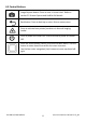
4.2 Control Buttons Image Capture button: Press to save a ‘screen-shot’. Refer to section 5.5 Screen Capture and Hold for full details. Back button. Press to back up or return from a menu screen. Press to activate laser pointer/crosshairs in thermal imaging modes. Press to power the meter ON. Press and hold to power the meter OFF. Press the Select button (center) to access the Main Menu. Use this button to select items from within the menu structure.
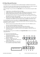
4.3 Menu Map and Overview The Menu structure is outlined below and covered thoroughly in subsequent sections of this User Guide. The center Select button and the four (4) Navigation buttons are used to access and program the modes of operation available from the menus. Refer to Fig. 4-2. Icons 1 through 5 in Fig. 4-2 make up the Main Menu. Press the Select button to open the Main Menu: 1. 2. 3. 4. 5.
5. Operation Important Note: Please charge the meter’s battery before first use. Instructions for battery charging are provided in Section 6.2. 5.1 Powering the Meter 1. Press the Power button 2. 3. Press and hold the Power button for > 1 second to switch the meter OFF. If the battery status indicator shows that the battery voltage is low, or if the meter does not power on, charge the battery. See section 6.2 Battery Charging.
5.2.2 Moisture Displays Overview There are three modes where moisture readings are displayed; refer to Figs. 5-1 (a) through (c) for a description of each. To access the modes shown below, press the Select button after navigating to the Image Mode icon in the Main Menu. Then use the navigation buttons to scroll to the desired mode; press Select again to confirm. Fig. 5-1(a) IGM Moisture Image Mode 1. Relative icon and reference value 2. Alarm icon and Alarm Threshold value 3.
1. Moisture reading (digital) 2. Moisture reading (bargraph); Bars are blue in color when in non-alarm state and red when in an alarm state. 3. Selected Moisture Mode 4. High Moisture Alarm threshold (see Section 5.8) 5. Set Reference value (see Set Fig. 5-1(c) Moisture-only Mode Reference mode in Sections 5.2.3 and 5.2.6); pinless mode only. Note that in Pin mode this display area will show the selected Material/Wood Group. Access the Moisture Mode to select the Material/Wood Group. 5.2.
5. Psychometrics mode In the Psychometrics mode the IR Thermal Camera Image is off and the meter displays all parameters except moisture (Air Temperature, RH%, Dew Point Temperature, Mixing Ratio, and Vapor Pressure). See Fig. 5-3. 6. Moisture reading only In the Moisture only mode the IR Thermal Fig. 5-3 Psychrometrics Screen Camera Image is off and the meter shows only the moisture reading in digits and in bargraph formats, see Fig. 5-1(c). 5.2.
5.2.5 Internal Moisture Sensor Measurements (Pinless) 1. Follow the steps in Section 5.2.1 through 5.2.4 and select the Pinless mode. 2. Place the internal moisture sensor (back) on the surface of the material to be tested. Apply light pressure to ensure that the internal sensor is completely flat against the surface of the material under test. 3.
5.2.7 Reference Mode Moisture Measurements 1. Follow the steps in Section 5.2.1 through 5.2.4 and select SET REFERENCE from the MOISTURE mode options. This mode is only available for pinless measurements (internal sensor). 2. When the SET REFERENCE mode is selected the displays are affected in the following ways: IGM Moisture image mode: A new display line will appear preceded by a delta (triangle) symbol.
Fig. 5-5 Thermal IR Image Color Palettes Fig. 5-5(a) - IRON PALETTE Fig. 5-5(b) - RAINBOW PALETTE Fig. 5-5(c) - ICE PALETTE Fig. 5-5(d) - GREY PALETTE When the Laser Pointer button is pressed, and held to activate the laser pointer, the display crosshairs also switch on, for additional targeting flexibility. Refer to Fig. 5-6. Note that the laser is carefully aimed to align with the crosshairs for easier identifying and targeting of objects and surfaces. 1.
5.4 Lock/Unlock Palette Auto-Scale Mode Note: For best results, allow a warm-up period of 3-5 minutes before using this feature. The Lock/Unlock Palette Auto-Scale option allows the color palette range to be adjusted to suit a given application. For example, when viewing both cold and hot objects in the same frame, the palette auto-scaling will cause the palette to be ‘stretched’ to fit the whole range of temperatures.
5.5 Screen Capture and Hold Pressing the Image Capture button captures the current MR176 screen. The screen will hold (freeze) for seven (7) seconds, until an image file-name appears indicating that the image has been saved. During the seven second ‘hold’ period, the user can simply examine the image and press the Back button to discard or press Select/Capture to save the image. Images are saved in bitmap (.bmp) format.
5.7 ‘Combination’ Feature: Save Thermal Image with Pinless Moisture Reading The Combination feature allows the user to ‘freeze’ a thermal image and take a moisture reading, saving both the thermal image and the moisture reading on a single image. The ‘held’ thermal image, with continuous moisture reading shown on the same screen, can then be captured as explained in Section 5.5 above. 1. Enter the IGM Moisture or IGM Custom Image mode (refer to Section 5.2.3 Image Mode). 2.
5.8 High Moisture Alarm The MR176 offers a High Moisture Alarm where an audible and visual alert activates when the moisture reading exceeds the programmed high limit. 1. Press the Select button to access the Main Menu 2. Select the SETTINGS mode 3. Scroll to ALARM and press the Select button to open the Alarm programmer 4. Use the Navigation and Select buttons to switch the alarm ON or OFF and to set the threshold from 0% to 100% 5.
3. PALETTE. Select the desired color scheme for the IR Thermal images. From the Settings menu scroll to the Palette selection and use the Select button to step through the IRON, RAINBOW, ICE, and GREY selections. Refer to Fig. 5-5 for example palette screens. Navigate to another Settings option or press the back button to exit the Settings menu. 4. ALARM. Set a high alarm threshold. From the Settings menu, scroll to Alarm and press the Select button.
6. Maintenance 6.1 Cleaning Clean the meter with a damp cloth and mild detergent; do not use abrasives or solvents. 6.2 Battery Charging 1. 2. 3. 4. 5. The internal battery is not user serviceable. Please charge the battery before first use. Connect the meter to an AC source or a computer USB port using the supplied USB charger cable. The USB port is located on the bottom of the meter, under the protective flap, next to the EXT Probe jack.
6.3 Updating the MR176 firmware The MR176 firmware can be updated in the field by the user, without the need for sending the unit in for service. If assistance is required, the user can contact a FLIR technical specialist (see Section 8). Firmware updates provide performance enhancements and new features and functions. To update the firmware, the following is required: Access to the website where the update file(s) are located: http://support.flir.
7. Specifications General Specifications Display Internal memory Stored image format Power supply Battery life Auto Power OFF Low battery indicator QVGA (320 x 240 pixel) 2.3” 64K color TFT graphical display 4GB; Storage capacity is 9999 images Bitmap (.bmp) with measurement values overlaid 3.
Moisture Meter Specifications Internal Pinless Sensor Measurements 0 to 100 (relative readings) External Pin-based Measurements Measurement Resolution Pinless Measurement Depth Pin Moisture Groups Response time 7% - 30%* (±1.5% MC*) 30%-100%* (Reference Only) 0.1 0.75” (1.9cm) maximum Nine (9) material groups Pinless mode: 100ms Pin mode: 750ms Notes: * Maximum specified range is dependent on the fiber saturation point for specific species.
8. Technical Support Main Website http://www.flir.com/test Technical Support Website http://support.flir.com Technical support Email TMSupport@flir.com Service/Repair Support Email Repair@flir.com Support Telephone number +1 855-499-3662 option 3 (toll-free) Firmware Updates To check for MR176 firmware updates please visit the technical support website (above) for complete installation instructions.
9. Material Groups 9.1 Common Names of Timbers (BS888/589:1973) with MR176 Group Nos. Note: GROUP 9 is for Building materials: Plywood, drywall, Oriented strand board (OSB), etc.
Cordia, American Light 5 Missanda 3 Sen 1 Cypress, E African 1 Muhuhi 8 Seraya, Red 3 Cypress, Japanese (18-28%mc) 3 Muninga 6 Silky Oak, African 3 Cypress, Japanese (8-18%mc) 8 Musine 8 Silky Oak, Australian 3 Dahoma 1 Musizi 8 Spruce, Japanese (18-28%mc) 3 Danta 3 Myrtle, Tasmanian 1 Spruce, Japanese (8-18%mc) 8 Douglas Fir 2 Naingon 3 Spruce, Norway (European) 3 Elm, English 4 Oak, American Red 1 Spruce, Sitka 3 Elm, Japanese Grey Bark 2 Oak, American Whi
9.
Castanea sutiva 3 Larix occidentalis 5 Scottellia coriacea 4 Cedrela odorata 8 Liquidamper styraciflua 1 Sequoia sempervirens 2 Ceratopetalum apetala 6 Lovoa klaineana 8 Shorea spp 2 Chamaecyparis spp (18-28%mc) 3 Lovoa trichiloides 8 Sterculia rhinopetala 1 Chamaecyparis spp (8-18%mc) 8 Maesopsis eminii 8 Swietenia candollei 1 Chlorophora excelsa 5 Mansonia altissima 2 Swietenia mahogani 2 Cordia alliodora 5 Millettia stuhimannii 1 Syncarpia glomulifera 3 Croton me
9.3 %WME Table (% Wood Moisture Equivalent) Material Wood Group Nos. 1 2 3 4 5 6 7 8 9 %WME (percent wood moisture equivalent) 7 8.2 9 8 7.1 7 11 10.5 - 8 10 10.5 9.3 7.5 7.4 11.5 11 - 9 10.8 10.9 9.7 7.9 8.1 12.1 11.6 8.5 10 11.7 11.5 10.4 8.6 8.8 12.7 12.2 9.4 11 12.7 12.6 11.3 9.5 9.7 13.4 13.4 10.5 12 13.6 13.7 12.1 10.5 10.5 14 14.3 11.5 13 14.5 14.5 12.7 11.2 11.2 14.5 15.1 12.5 14 15.3 15.5 13.4 11.8 11.8 15 16 13.
10. Warranty 10.1 FLIR Test & Measurement 2 year/10 year Limited Warranty Congratulations! You (the “Purchaser”) are now the owner of a world-class FLIR Imaging Test and Measurement product. A qualifying FLIR Imaging Test and Measurement product (the “Product”) purchased either directly from FLIR Commercial Systems Inc.
6. WARRANTY RETURN, REPAIR AND REPLACEMENT. To be eligible for warranty repair or replacement, Purchaser must notify FLIR within thirty (30) days of discovering of any apparent defect in materials or workmanship. Before Purchaser may return a Product for warranty service or repair, Purchaser must first obtain a returned material authorization (RMA) number from FLIR. To obtain the RMA number Owner must provide an original proof of purchase.
Corporate Headquarters FLIR Systems, Inc. 2770 SW Parkway Avenue Wilsonville, OR 97070 USA Telephone: +1 503-498-3547 Customer Support Technical Support Website Technical Support Email Service and Repair Email Customer Support Telephone http://support.flir.com TMSupport@flir.com Repair@flir.com +1 855-499-3662 option 3 (toll free) Firmware Updates To check for MR176 firmware updates please visit the technical support website (above) for complete installation instructions. Publication Identification No.