
User Manual


FLIR MR60 USER MANUAL Document Identifier: MR60-en-US_AB
11
5.2.4 External Pin Probe Moisture Measurements
1. Follow the steps in Section 5.2.1 through 5.2.3 and select Pin mode from the MOISTURE
mode options.
2. Connect the external pin probe to the meter’s EXT jack on the bottom of the meter
(under the protective flap). Refer to the FLIR website for information on available
external pin moisture probe types.
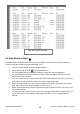
3. Select the appropriate Material Group as described in Section 5.2.3 (see Section 9 for the
Material Group Appendices). Note: Use Group 10 for brick, cement, screed, and
concrete. Use Group 11 for cement mortar, anhydrite screed, and lime.
4. Press the pins into the material under test. When using Group 10 or Group 11 it is
recommended that a conductive paste be used to ensure good contact.
5. The moisture reading is displayed on the main display (%) and as a bargraph, similar to
the display example shown in Fig. 5-1.
Notes on External Pin Probe Moisture measurements
The MR60 will display accurate external pin probe readings in the 7% to 30% range, depending on the
tested material. Moisture Content readings below 6% will display as 0% for all materials and the
maximum specified range is dependent on the fiber saturation point for specific species. Above the fiber
saturation point, the reading can only be used as a relative reference value.
For more information on fiber saturation please refer to ASTM D7438. For additional information on Pin
moisture measurement accuracy please see ASTM D4444, section 6.
Notes on Material Groups 10 and 11
Groups 10 and 11 provide basic moisture content estimations in the range of 0~20% (Group 10) and
0~9% (Group 11). These readings can be used to identify problem areas but should be verified using an
RH-type concrete moisture meter per ASTM F2170. As such, even though the readings are presented in
%MC by weight, they should be considered for reference only.
5.2.5 Internal Moisture Sensor Measurements (Pinless)
1. Follow the steps in Section 5.2.1 through 5.2.3 and select the Pinless mode.
2. Place the internal moisture sensor (back) on the surface of the material to be tested.
Apply light pressure to ensure that the internal sensor is completely flat against the
surface of the material under test.
3. The relative moisture reading is displayed on the main display, digitally and as a color-
coded bargraph (blue when not in an alarm state; red when in an alarm state). Refer to
Fig. 5-1.
4. Keep hands, surfaces, and objects away from the rear internal moisture sensor area
when taking measurements.
5. For best results, lift the meter off of the surface under test between measurement
points; do not drag the meter over surfaces.