427-0075-01-12 Revision 140 October 2019 This document does not contain any export-controlled information.
427-0075-01-12 Revision 140 October 2019 This document does not contain any export-controlled information.
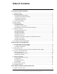
Table of Contents PT-Series HD Camera Installation 1.1 Camera Overview ......................................................................................................................5 1.2 Installation Overview ..................................................................................................................5 1.2.1 Camera Connection Options ............................................................................................5 1.2.2 Serial Communications Overview ...............
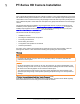
PT-Series HD Camera Installation The PT-Series HD pan/tilt thermal security camera for medium- to long-range applications can be used with traditional analog video installations or IP video networks. It incorporates a high-sensitivity thermal camera with a choice of lenses and a long-range daylight camera all within a precision pan/tilt platform. The PT-602CZ HD pairs a cooled mid-wave focal plane array (FPA) thermal detector with the daylight camera.
PT-Series HD Camera Installation 1.1 Camera Overview The PT-Series HD camera is both an analog and an IP camera. The video from the camera can be viewed over a traditional analog video network or it can be viewed by streaming it over an IP network using MJPEG or H.264 encoding. Analog video will require a connection to a video monitor or an analog matrix/switch. The IP video will require a connection to an Ethernet network switch and the appropriate software for viewing the video stream. 1.
PT-Series HD Camera Installation Network Security The camera supports IEEE 802.1x authentication when connected to a network supporting the following requirements: • Network device (Authenticator) such as an Ethernet switch configured with 802.1x • Authentication server supporting either TLS Refer to 1.2.2 for information on how to configure the LAN settings.
PT-Series HD Camera Installation • Shielded CAT6 Ethernet cable for streaming video, control, and for software updates. CAT5e Ethernet cable may be adequate in many installations except when closely installed with power cables in demanding video streaming networks. • Serial cable for serial communications—optional • Miscellaneous electrical hardware, camera mount (with stainless steel washers and bolts), connectors, and tools 1.
PT-Series HD Camera Installation steel fasteners and the aluminum camera base, and electrically isolates the complete PT-Series HD camera from the customer mount. Galvanic isolation is critical in preventing corrosion. Proper installation of galvanic isolation pad and washers is important for long product life. Refer to for specific instructions. 1.5.
PT-Series HD Camera Installation PT-Series HD cameras must be mounted upright on top of the mounting surface, with the base below the camera. The unit should not be hung upside down. Not to scale All dimensions in inches Pan volume minimum Ø25.5 2X 2.72 ± .02 2X 2.72 ± .02 4X Ø.354 THRU 0 2X 3.17 ± .02 Tilt Axis 0 0.295 2X 3.21 ± .02 Pan Axis Figure 1-2: PT-Series HD Camera Mounting 1.5.
PT-Series HD Camera Installation • Once the mounting location has been selected, verify both sides of the mounting surface are accessible and free of utility service lines or other obstructions. • Use stainless steel hardware to fasten mounts to outdoor surfaces. • Use a thread locking compound such as Loctite 242 or equivalent with all metal to metal threaded connections.
PT-Series HD Camera Installation Step 5 Ensure the camera is properly grounded. FLIR requires using a 14 AWG to 16 AWG grounding strap anchored to the ground lug on the back plate of the camera housing and then terminated to the nearest earth-grounding point. M8 or 5/16” fasteners (not supplied) 4 places, minimum length 1 in. (dependent on mounting structure) If using nylon flat washers, apply a generous coat of Tef-Gel filling all gaps and voids.
PT-Series HD Camera Installation 1.6 1.6.1 Camera Connections Remove the Back Cover Use a 2.5 mm hex key to loosen the captive screws and remove the cover, exposing the connections at the back of the camera.
PT-Series HD Camera Installation 3/4” NPT for Cable Gland or Conduit Figure 1-5: PT-Series HD Camera Connection Schematic 1.6.2 Connecting power The camera itself does not have an on/off switch. Generally a circuit breaker will be used to apply or remove power to the camera. If power is supplied to it, the camera will be in one of two modes: Booting Up or Powered On.
PT-Series HD Camera Installation Lens Heaters The lens heaters are intended to provide lens de-fogging and de-icing in the event of: • A power interruption which disables the camera for an extended period, and • Freezing rain which fully covers the lens and obstructs the image. The PT-Series HD cameras are shipped from the factory with the lens heaters enabled. The lens heaters are configured to dynamically maintain the camera window at a constant temperature.
PT-Series HD Camera Installation Note The serial communications parameters for the PT-Series HD camera are set or modified either via hardware DIP switch settings or via software, through a web browser interface. A single DIP switch (SW103-9), Software Override determines whether the configuration comes from the hardware DIP switches or the software settings. Note The DIP switches are only used to control serial communications parameters.
PT-Series HD Camera Installation Table 1-2: Dip Switch Address/ID Settings—SW101 Other Serial Communication Parameters: The tables below defines the switch locations, bit numbering and on/off settings used in controlling the other serial communication parameters.
PT-Series HD Camera Installation 1.6.7 Back Cover Gasket When preparing to re-attach the back cover, make sure that the gasket rests securely in the groove so that attaching the cover does not cut or otherwise damage the gasket. The picture below shows the black gasket properly in place. If possible, lay the camera down to install the gasket and cover. If doing so is not possible, before installing the cover, apply a small amount of O-ring lubricant to the gasket to help hold it in place. 1.6.
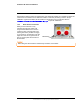
PT-Series HD Camera Installation Cable Gland Seal Inserts Cables may be between 0.23" to 0.29" OD. Up to six cables may be installed. Plugs are required for the hole(s) not being used. The photograph at the right shows two power cables, an Ethernet cable, an analog video cable, and two gland seal plugs. Gland seal plugs Ground Lug Analog video Camera Power If non-standard cable diameters are used, it may be necessary to locate or fabricate the appropriate insert to fit the desired cable.
PT-Series HD Camera Installation 1.7 PT-Series HD Camera Specifications Uncooled Thermal Camera Model FOV Focal Length Optical Characteristics Visible Camera Cooled Thermal Camera PT-602CZ HD Compliance and Certifications 427-0075-01-12 Revision 140 October 2019 This document does not contain any export-controlled information.
PT-Series HD Camera Installation Video System Integration Pan/Tilt General Environmental Method 514.6, Procedure 1b a. Power consumption is independent of the input voltage when the heater is off. The power drawn by the heaters increases with the input voltage to a maximum at 30 Volts. 427-0075-01-12 Revision 140 October 2019 This document does not contain any export-controlled information.
Basic Operation and Configuration This chapter provides basic information on how to operate the PT-Series HD camera. A bench test can be used to verify camera operation before the camera is configured for the local network. This chapter also provides general configuration information. 2.
Basic Operation and Configuration Once the camera is connected to a network and powered on, set camera network parameters using the FLIR Discovery Network Assistant (DNA) software, perform a bench test by using a web browser to view the video and control the camera, or view video in the local Network Video Management System (for example, FLIR Latitude). The FLIR Discovery Network Assistant (DNA) software does not require a license to use and is a free download from the individual product web page at: . 2.
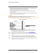
Basic Operation and Configuration Step 4 Step 5 Double-click the camera in DNA’s Discovery List to open the camera’s web server Login page in a web browser, or point a web browser to the camera’s IP address. Step 6 Using a web browser, configure the camera settings, such as camera date/ time, and other parameters, so the camera is compatible with the existing network. 2.
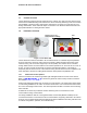
Basic Operation and Configuration 2.3.1 Live Video Page The Live Video page displays a live image from the camera on the left part of the screen. Along the top of the screen are some menu choices, including Live Video (the red text indicates it is selected), Help and Log out. On the right side are control buttons and a virtual joystick (for pan/tilt capability). Toggle Time Figure 2-1: Live Video Web Page – user login In the lower right corner of the web page there is a frame rate selector.
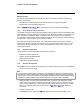
Basic Operation and Configuration 2.3.2 Camera Control and Status In the lower left of the screen are two indicator lights: Control and Status. Initially the Control light is off, as in the image above, indicating the user is not able to control the camera immediately. When multiple users are connected to a camera, only one user at a time can issue commands to the camera. If another user has control of the camera, the Control light is yellow.
Basic Operation and Configuration The functions of the buttons appearing for the PT-Series HD cameras are described below: Zoom In/Zoom Out These buttons zoom the active camera (IR or daylight). On cameras with optical zoom lenses, digital zoom or E-Zoom extends the ability to zoom in beyond the optical zoom range, but at the expense of resolution. Also, refer to . Toggle Video Source This button causes the active video source to be switched between the thermal IR camera and the daylight camera. Refer to .
Basic Operation and Configuration Autofocus This button causes the DLTV camera to toggle the autofocus mode. Clicking the button a second time reinstates the autofocus mode and causes an autofocus operation. This button causes the IR camera with a zoom lens to perform a one-time autofocus operation. Perform IR NUC Calibration—IR only—not present for PT-602CZ HD This button causes the camera to do a manual Non-Uniformity Correction (NUC) operation.
Basic Operation and Configuration Note In most installations, the only camera settings needed are available from the Live Video page (using Scene Presets or Polarity). Use caution when modifying the camera settings described in this section. Some settings may adversely affect the thermal image over time or may completely disable the camera or the network interface. 2.4.1 Expert and Admin Accounts When a user logs in as expert or admin, additional menus, Setup and Maintenance are available.
Basic Operation and Configuration 2.4.2 The zones. Setup Menu menu is used for GEO Settings, camera setup, and defining parameters for surveillance When configuration changes are made with the web browser, the settings are saved to a configuration file. It is a good idea to make a backup of the existing configuration file prior to making changes, and another backup once the changes are finalized.
Basic Operation and Configuration To modify parameters that affect a particular IP Video stream from the camera, select the appropriate link (for example, ). The default parameters provide high-quality full frame-rate video streams with reasonable bandwidth usage. In general, for most installations it will not be necessary to modify the default parameters.
Basic Operation and Configuration The parameters in the Encoding section will have a significant impact on the quality and bandwidth requirements of the video stream. In general it is recommended that the default values are used initially, and then individual parameters can be modified and tested incrementally to determine if the bandwidth and quality requirements are met. For the video streams, the Codec options are H.264 Main or MJPEG.
Basic Operation and Configuration For enhanced security, RTSP authentication can be enabled. There are some challenges with streaming video over an IP network, when compared to applications which are less time-critical, such as email and web browsing. There are requirements which must be fulfilled to ensure satisfactory video quality in professional security environments.
Basic Operation and Configuration IR > AGC The AGC parameters affect how the overall IR video image appears. Using the AGC button on the Live Video page (refer to ), toggle through five AGC algorithms. The default algorithms are suitable for most installations, but each selection allows a combination of further adjustments that may provide a more appealing image, depending on personal preferences.
Basic Operation and Configuration Surveillance > Scan List To setup Presets: position camera, select Preset ID Click Set Surveillance > Auto Scan To start Auto Scan: select width and speed, then select Start Set Autoscan parameters: select speed, select limits, click Save Relative Auto Scan (Surveillance mode) will scan the scene starting with the current position of the camera. Absolute Auto Scan will scan the scene starting with the zero azimuth position of the camera.
Basic Operation and Configuration Server > LAN Settings The page can be used to set the hostname, default gateway, and IP address for the camera. Scroll down to see settings for Domain Name System (DNS) server and 802.1x Security. IP Address When set to DHCP, if the network does not have a DHCP server, the PT-Series HD camera will default to an IP address of 192.168.0.250. To set the IP address using DNA, refer to .
Basic Operation and Configuration To configure 802.1x security on the LAN using TLS authentication: Step 1 On the LAN Settings page, scroll down to 802.1X Security. Step 2 Select the Use 802.1x security checkbox. Step 3 From the Authentication drop-down menu, select TLS. Step 4 In the Identity text box, enter a name to associate with the camera.
Basic Operation and Configuration Server > Services > Date and Time The date, time, and time zone can be obtained from an NTP server, or can be entered manually. If the NTP mode is selected, the NTP server information can be entered. The NTP server address can be entered as a static address or can be obtained via DHCP. Note The server must be stopped before date and time settings can be changed. Set the date and time parameters, then select the Save button at the bottom.
Basic Operation and Configuration Server > Services > Systems Use the notifications. page to set up a connection to a mail server to send outgoing email If the email server is on a different network, ensure the IP default gateway and DNS servers are configured in the LAN Settings; refer to . Configure the Msg Systems page with mail server information and then click Save.
Basic Operation and Configuration Server > Services > TLS Config The settings on this page enable secure, encrypted communication between clients and the camera; for example, when your web browser accesses the camera’s web interface. Note The camera also supports TLS authentication over the camera’s LAN. For information about configuring TLS authentication for LAN communication, see . By default, TLS is disabled. Before enabling it, you need to generate or upload a valid certificate.
Basic Operation and Configuration To generate and install a self-signed certificate: Step 1 Under Generate Certificate, for Method, select Self-Signed. Step 1 Enter information such as country code, city name, and organization name. Step 2 Scroll to the bottom of the page and click Generate Certificate. Step 3 Allow 15 seconds for the camera to generate the certificate, at which point a confirmation appears.
Basic Operation and Configuration Certificate information appears at the bottom of the TLS Config page, under Certificate Information: To enable and configure TLS: Step 1 Under TLS Configuration, for Enabled, select Yes. Step 2 Select whether to redirect HTTP requests to HTTPS. Step 3 Click Save. Step 4 Click Reboot. The camera reboots. After the camera reboots, TLS is enabled.
Basic Operation and Configuration After making configuration changes, it is necessary to save the changes to the server (there is a Save button at the bottom of each configuration page). The configuration changes do not take effect immediately. Generally, it is also necessary to stop and restart the server for the changes to become effective. The server has a configuration that is active and running, and another configuration that is saved (and possibly different than the running configuration).
Basic Operation and Configuration Restrict web configuration Add IP address The admin login can limit which computers have access to the web browser interface. Simply add a computer’s IP address and click Add. After all the allowed IP addresses are entered, click Save to save the changes. Password management To maintain security of the system, set new passwords for all of the login accounts. • —Used for ONVIF communication. • • —The user account can only use the page and controls.
Basic Operation and Configuration Firewall settings For enhanced security, a firewall can be enabled (by scrolling down on the Security Options page). With the firewall enabled, you can open the following services and their default ports by selecting Enabled: • RTSP • SSH • uPnP Discovery • Nexus SDK • TRK Interface Select Yes Important Note Nexus CGI digest authentication Below the firewall settings, you can enable Nexus CGI digest authentication.
Basic Operation and Configuration Sensor > Communications > Serial Remote Bosch settings Pelco-D settings Select protocol Save Toggle Server (Stop/Start) Sensor > Communications > VMS Remote The VMS Remote page provides communication interfaces for devices that connect to the camera. Authentication when enabled uses the same passwords set from the Server Security Options page. Refer to .
Basic Operation and Configuration ONVIF Interface The ONVIF (Open Network Video Interface Forum) is an open industry forum for the development of a global standard for the interface of network video products. An ONVIF-compliant VMS can be used to control a FLIR camera. Refer to the VMS documentation to determine what parameters are needed. By default, the camera is configured with a VMS Remote interface with ONVIF 2.0 parameters (Profile S).
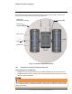
Basic Operation and Configuration Sensor > Devices > Pan & Tilt Scroll down to select an action the camera will perform at startup (power cycle or server reset). Scroll down to Save Select an action from the menu Sensor > Modules > Video By default, four video streams are enabled for the camera: Video 0, Video 1, Video 2, and Video 3. The streams are available for viewing from a client program such as FLIR Latitude, a stand-alone video player, or a third-party VMS including ONVIF systems.
Basic Operation and Configuration To modify parameters that affect a particular IP Video stream from the camera, select the appropriate link at the top of the page (for example, ). The default RTP Settings for connecting to an IP video stream from the PT-Series HD are shown in the illustration. The RTP Port and the Stream Name are used when establishing a session from a client. Given the camera IP address of 192.168.0.
Basic Operation and Configuration The time-to-live field controls the ability of IP packets to traverse network boundaries. A value of 1 restricts the stream to the same subnet. Greater values allow increasing access between networks. The video streaming is done using a protocol generally referred to as Real-time Transport Protocol (RTP), but there are actually many protocols involved, including Real-Time Transport Control Protocol (RTCP) and Real Time Streaming Protocol (RTSP).
Basic Operation and Configuration 2.4.4 Files Menu The administrative actions for accessing, updating, and transferring files are accessed through the menu on the left side of the page. Selected actions from the Firmware, , and Log pages are described below. Stop server Files > Firmware For camera firmware updates, manually install a firmware update file by first stopping the camera server, browsing to select the update file on your computer, and selecting Upload.
Basic Operation and Configuration is the configuration script file in a scrollable window. This can be useful if help is ever needed from a support engineer. In the Backup & Recovery section, click the Restore link associated with the factory.defaults configuration to restore the camera to its factory settings. This file can not be modified or deleted, so it is always available. Use the Backup button to make a backup of the final settings.
Basic Operation and Configuration Files > Log > Field Support Log Scroll down and select the button under Field Support Log to download a zip file to the computer for field service evaluation. 2.5 Thermal Imaging Overview PT-602CZ HD Only—When power is applied to the PT-602CZ HD camera, a compact integral Stirling cooler (also known as a cryocooler) starts automatically.
Basic Operation and Configuration On the other hand, the thermal camera detects energy that is directly radiated from objects in the scene. Most objects in typical surroundings are not hot enough to radiate visible light, but they easily radiate the type of infrared energy that the thermal camera can detect. Even very cold objects, like ice and snow, radiate this type of energy.
Basic Operation and Configuration the day due to solar loading. Greater temperature differences in the scene generally will allow the camera to produce higher-contrast imagery. Performance may also be affected when objects in the scene are wet rather than dry, such as on a foggy day or in the early morning when everything may be coated with dew. Under these conditions, it may be difficult for the camera to show the temperature the object itself, rather than of the water coating.
Basic Operation and Configuration Check cable connector terminations. Inferior quality connections may use multiple adapters which can cause unacceptable noise. Use a high-quality video distribution amplifier when splitting the signal to multiple monitors. Image too dark or too light: By default the PT-Series HD thermal camera uses an Automatic Gain Control (AGC) setting that has proven to be superior for most applications, and the camera will respond to varying conditions automatically.
Serial Address: Decimal To Binary Conversion Note, the order of the switches 1-8 is the reverse of the binary digits. For example, for address 1 the binary equivalent is 00000001 and the left-most switch (switch1) is on. 3.
Serial Address: Decimal To Binary Conversion 427-0075-01-12 Revision 140 October 2019 This document does not contain any export-controlled information.
FLIR Systems, Inc. 6769 Hollister Ave Goleta, CA 93117 USA Corporate Headquarters FLIR Systems, Inc. 27700 SW Parkway Ave. Wilsonville, OR 97070 USA Support: Document: 427-0075-01-12 Revision: 140 Date: October 2019 This document does not contain any export-controlled information.