
User Guide


427-0075-01-12 Revision 140 October 2019 6
This document does not contain any export-controlled information.
PT-Series HD Camera Installation
Network Security
The camera supports IEEE 802.1x authentication when connected to a network supporting the
following requirements:
• Network device (Authenticator) such as an Ethernet switch configured with 802.1x
• Authentication server supporting either TLS
Refer to for information on how to configure the LAN settings.
1.2.2 Serial Communications Overview
The installer must decide if the serial communications settings will be configured via hardware (DIP
switch settings) or software (default). If the camera has an Ethernet connection, then generally it is
easier (and more convenient) to make configuration settings via software. Then configuration
changes can be made over the network without physically accessing the camera. Also the settings
can be saved to a file and backed up or restored as needed.
If the camera is configured via hardware, then configuration changes in the future may require
accessing the camera on a tower or pole, dismounting it, and removing the back and so on. If the
camera does not have an Ethernet connection, the DIP switches must be used to set the serial
communication options.
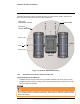
1.2.3 Supplied Components
The PT-Series HD camera ships with these standard components:
• Multi-sensor pan/tilt camera unit
• Galvanic isolation kit (PN 4204960)
• Noise suppression ferrite
• Cable glands and spare parts kit
1.2.4 Required Components
The installer will need to supply the following items; the cable lengths are specific to the installation.
• 24 Vdc or 24 Vac power supply
Note
• Electrical cables, for system power and heater power; 3-conductors are required for system
power (one ground) and two conductors are required for heater power (no ground). The wire
gauge must be determined by cable length and supply voltage. A single 5-conductor, shielded
cable or two individual cables may be used. Refer to for additional
information.
• Camera grounding strap
• Coaxial RG59U video cables and a BNC adapter at the camera end for analog video
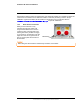
A single ferrite is supplied with this equipment, the equipment was tested for compliance with the
FCC limits for a Class A digital device using the ferrite installed on the system power cable. When
connecting one or two power cables to the equipment, the supplied ferrite must be installed with this
equipment. A power installation using metal conduit does not require installing the ferrite.