FLO Home X5 Model Installation guide
Languages English 3 Français Assistance A customer experience or technical support representative can assist you! Customer and Technical Support For any questions regarding charging station installation, configuration or any technical problem. 1-855-543-8356 You can also contact us at: service@flo.
Table of Contents Safety Instructions 4 Before You Install 5 Box Contents 6 Installing the Station 7 Wiring the NEMA 6-50 Power Cord Plug 9 Installing the PLC 10 Connect the Station to your Account 12 Light Indicators 14 Sound Indicator 15 Installing a Second Station 16 Charging Station Serial Number 17 Warranty - USA 18 Warranty - CA 20 Casing: 100% aluminum NEMA 4X Certified, designed for outdoor or indoor installation Finish: Metallic Grey (CA), Tungsten or Carbon (US) with hig
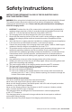
Safety Instructions INSTRUCTIONS PERTAINING TO A RISK OF FIRE OR ELECTRIC SHOCK SAVE THESE INSTRUCTIONS! WARNING: When using electrical appliances, basic precautions should always be followed. This manual contains important instructions that must be followed when installing, operating and maintaining the unit. Please read this guide carefully before attempting to install the charging station. 1.
Before You Install IMPORTANT CONSIDERATIONS WHEN INSTALLING THE STATION The station must be installed by a certified electrician. The station has built-in protection against overvoltage conditions and leakage current to ground. Any alteration to any part of the charging station will void the warranty.
Box Contents 1. Charging station 2. Cable and charging connector 3. Wall mounting plate 4. PLC Module and Ethernet Cable 5. Card with association code 6. NEMA 6-50 Power Cord Plug (for US Models Only) Recommended height to facilitate handling of the connector, as well as preventing the cable from touching the ground. 7.6 in 19.3 cm 6.9 in 17.5 cm 17 in 43.2 cm 60 in 152.4 cm Floor 6 January 2019 | flo.
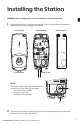
Installing the Station WARNING: Your charging station must be installed by a licensed electrician. 1 Disassemble the front casing by removing the 2 front screws and then separate the mounting plate by unscrewing the lower screw.
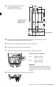
3 Hang the mounting plate securely 178 mm / 7.62" to a stable surface using a minimum of 3 anchor screws. 51 mm 2.25" 152 mm 6.00" Anchoring screws Mininum of 3 Maximum of 6 406 mm 16.96" 27 mm 1.06" 152 mm 6.00" 42 mm 1.69" 107 mm 4.22" Wall structure 4 Insert the conductors and secure the strain relief to the rear housing so that the conductors are long enough to reach the terminals. 5 Secure the rear housing of the station to the mounting plate.
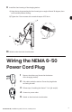
Install the front housing of the charging station: A) Hang the top by presenting the front housing at an angle of about 30 degrees, then pivot vertically without forcing. B) Tighten the 2 front screws with a nominal torque of 55 lbs-in. A B Detail A About 30° 10 Switch on the electrical circuit breaker. Wiring the NEMA 6-50 Power Cord Plug 1 Remove the rubber cap (located at the bottom of the charging station). 2 Pull cables inside the station. Ensure the plug blades are facing the wall.
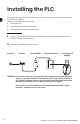
Installing the PLC To connect your new FLO Home X5 station to your FLO account, you must first connect the PLC module (included). To do this, you will need the following: 1. Internet access 3. A free wall power outlet near your router 2. A free Ethernet socket on your router 1 Connect one end of the Ethernet cable (included) to your PLC module and the other end to a free port on your router. 2 Plug the PLC module into a wall outlet.
3 Testing the PLC Connection The station and the PLC module are preconfigured at the factory to connect automatically. After 30 seconds, check that the 3 LEDs of the PLC module are all lit. 1 2 The three lights lit up indicates that the connection was successful. 3 1 Power LED - SOLID: The device is receiving electrical power. - BLINKING: The device is resetting, the simple connect button was pressed or power saving mode was enabled. - OFF: The device is not receiving electrical power.
Connect the Station to your FLO Account When your station is powered and the PLC module is installed, the station automatically connects to the Internet. Simply connect to your FLO account to access your new station. If your new station is not present in your account, you can add it using the association code that is included in the box. 1 If you have not already done so, you can create your FLO account. Go to flo.ca/signup (CA) or account.flo.com/Account/SignUp (USA) and follow the instructions.
4 Enter the 16-character association code on the included card with your new station and click “Associate”. 5 A message confirming the association should appear. Otherwise, contact our technical support for assistance. FLO Home X5 | Installation guide | flo.
Station Status light indicator Green - Solid color (not blinking): powered station, ready for use - Blinking slowly: vehicle charging completed White - Solid color (not blinking): connector connected to the vehicle, without energy transfer (waiting for the time schedule configured by the user) - Blinking quickly: session permission obtained (this state is created when using the mobile application or the user web portal to start a remote session) - Blinking slowly: waiting for an energy transfer reque
Sound Indicator - 1 short beep: start of power transfer to vehicle - 2 short beeps: modification of the current setpoint - 3 short beeps: end of energy transfer -1 long beep: major fault requiring a restart of the current session (please unplug the vehicle connector and restart your session) -2 long beeps: major fault requiring a power interruption (please restart the station by cutting the power at the circuit breaker in the electrical panel for 10 seconds, then restore power) FLO Home X5 | Installati
Installation of a Second Station Two FLO Home X5 can be connected to a separate or on the same 40 A circuit breaker via a junction . The first charging station will automatically detect the second. -P ower splitting only works with the FLO Home X5. -W hen 2 stations are connected to the same circuit breaker, their output current will be limited to 16 A each. - The two FLO Home X5 will synchronize automatically after the power is restored.
Charging Station Serial Number When contacting the customer or technical support, you may be required to provide your charging station serial number. If you do not know your charging station serial number, you can find it at the bottom of the charging station right beside the connector cable. If you have any problems locating the serial number, follow the procedure below.
Warranty USA Compliance 254081 IC statement: CAN ICES-3 (B)/NMB-3 (B) This device complies with Industry Canada licence-exempt RSS standard(s). Operation is subject to the following two conditions: (1) this device may not cause interference, and (2) this device must accept any interference, including interference that may cause undesired operation of the device.
4.Limited Remedies. If a Product is found by FLO after inspection to be defective or to not function in accordance with the Technical Specifications during the Warranty Period FLO’s sole obligation under this Warranty is limited to performing one of the following actions, at FLO’s sole and absolute discretion: (1) repairing; (2) replacing or (3) reimbursing the Purchaser for the purchase price of the Product, at FLO’s sole and absolute discretion.
Warranty CA Compliance 254081 IC statement: CAN ICES-3 (B)/NMB-3 (B) This device complies with Industry Canada licence-exempt RSS standard(s). Operation is subject to the following two conditions: (1) this device may not cause interference, and (2) this device must accept any interference, including interference that may cause undesired operation of the device. FCC statement (for USA only) This device complies with Part 15 of the FCC Rules.
4.Limited Remedies.
FLO Maison modèle X5 Guide d’installation
Table des matières Consignes de sécurité 24 Planification de votre installation 25 Contenu de la boite 26 Installation de la borne 27 Installation du cordon d’alimentation NEMA 6-50 29 Installation du CPL 30 Association de la borne à votre compte 32 Indicateurs lumineux 34 Indicateur sonore 35 Installation d’une deuxième borne 36 Numéro de série de la borne de recharge 37 Garantie 38 Boîtier : 100% aluminium certifié NEMA 4X conçu pour une installation extérieure ou intérieure Finit
Consignes de sécurité INSTRUCTIONS RELATIVES AUX RISQUES D’INCENDIE OU DE CHOC ÉLECTRIQUE CONSERVER CES INSTRUCTIONS AVERTISSEMENT : Lors de l’utilisation d’appareils électriques, des précautions de base doivent toujours être respectées. Ce manuel contient des instructions importantes qui doivent être suivies lors de l’installation, l’exploitation et la maintenance de l’appareil. Veuillez lire ce guide attentivement avant d’entreprendre l’installation de la borne de recharge. 1.
Planification de votre installation ÉLÉMENTS IMPORTANTS À CONSIDÉRER LORS DE L’INSTALLATION La borne doit être installée par un électricien agréé. La borne contient une protection intégrée contre les surtensions et les fuites de courant vers la terre. Toute modification d’une pièce de la borne de recharge en annulera la garantie.
Contenu de la boite 1. Borne de recharge 2. Câble et connecteur de recharge 3. Plaque de montage 4. Module CPL et câble Ethernet 5. Carte avec code d’association Hauteur recommandée afin de faciliter la manipulation du connecteur, en plus d’éviter au câble de toucher le sol. 7.6 in 19,3 cm 6.9 in 17,5 cm 17 in 43,2 cm 60 in 152,4 cm Floor 26 Janvier 2019 | flo.
Installation de la borne ATTENTION: Votre borne doit être installée par un électricien agréé. 1 Désassembler le boîtier avant en enlevant les 2 vis de façade puis séparer la plaque de montage en dévissant la vis inférieure.
3 Fixer la plaque de montage solidement à une surface stable en utilisant un minimum de 3 vis d’ancrage. 178 mm / 7,62" 51 mm 2,25" 152 mm 6,00" Vis d’ancrage Minimum de 3 Maximum de 6 406 mm 16,96" 27 mm 1,06" 152 mm 6,00" 42 mm 1,69" 107 mm 4,22" Structure murale 4 Insérer les conducteurs et fixer le serre-fils au boîtier arrière de façon à ce que les conducteurs soient assez longs pour atteindre les borniers. 5 Fixer le boîtier arrière de la borne à la plaque de montage.
9 Installer le boîtier avant de la borne de recharge : A) Accrocher le haut en présentant le capot à un angle d’environ 30 degrés, puis pivoter à la verticale sans forcer. B) S errer les 2 vis de façade avec un couple de serrage nominal de 55 lb-po. A B Détail A Environ 30° 10 Activer le disjoncteur du panneau électrique. Installation du cordon d’alimentation NEMA 6-50 1 2 Retirez le capuchon en caoutchouc (situé sous la station de recharge). Insérer les câbles à l’intérieur de la station.
Installation du CPL fin de raccorder votre nouvelle borne FLO Maison X5 à votre compte FLO, vous devez A connecter le module CPL (inclus). Pour ce faire, vous avez besoin des éléments suivants: 1. Un accès à Internet 3. Une prise d’alimentation électrique murale libre à proximité de votre routeur 2. Une prise Ethernet libre sur votre routeur 1 Relier une extrémité du câble Ethernet (inclus) à votre module CPL et l’autre extrémité à un port libre de votre routeur.
3 Vérification de la connexion du CPL La borne et le module CPL sont préconfigurés en usine pour se connecter automatiquement. Après 30 secondes, vérifier que les 3 voyants du module CPL soient tous allumés. 1 2 Les trois lumières allumées vous indiquent que la connexion est réussie. 3 - ALLUMÉ : Le périphérique reçoit une alimentation 1 Voyant d’alimentation électrique.
Association de la borne à votre compte FLO Lorsque votre borne est alimentée et le module CPL installé, la borne se connecte automatiquement à l’Internet. Vous n’avez qu’à vous connecter à votre compte FLO pour accéder à votre nouvelle borne. Si votre nouvelle borne n’est pas présente dans votre compte, vous pouvez l’ajouter à l’aide du code d’association inclus à l’intérieur de la boite de la borne. 1 Si ce n’est déjà fait, vous pouvez créer votre compte FLO.
4 Entrer le code d’association de 16 caractères se trouvant sur la carte incluse avec votre nouvelle borne, puis cliquer sur « Associer ». 5 Un message confirmant l’association devrait apparaitre. Autrement, contactez notre soutien technique pour obtenir de l’aide. FLO Home X5 | Installation guide | flo.
États de la borne Indicateurs lumineux Vert - couleur solide (ne clignote pas): borne alimentée, prête pour l’utilisation - clignote lentement: recharge du véhicule complétée Blanc - couleur solide (ne clignote pas): connecteur branché au véhicule, sans transfert d’énergie (en attente de la plage horaire configurée par l’usager) - clignote rapidement: autorisation de branchement obtenue (cet état est créé lorsqu’on utilise l’application mobile ou le portail web usager pour démarrer une session à dista
Indicateur sonore - 1 court bip : début du transfert de puissance au véhicule - 2 courts bips : modification de la consigne de courant - 3 courts bips : fin du transfert d’énergie - 1 long bip : faute importante nécessitant un redémarrage de la session en cours (veuillez débrancher le connecteur du véhicule et recommencer votre session) - 2 longs bips : faute majeure nécessitant une coupure d’alimentation (veuillez redémarrer la borne en coupant l’alimentation à l’aide du disjoncteur de la boite électriqu
Installation d’une deuxième borne Deux FLO Maison X5 peuvent être alimentées sur deux disjoncteurs distincts de 40 A d’un même panneau électrique ou sur un même disjoncteur de 40A via une boite de jonction. La borne de recharge détectera automatiquement si elle partage son circuit d’alimentation avec une autre FLO Maison X5. -L e partage de puissance ne peut être effectué qu’avec des bornes de recharge FLO Maison X5.
Numéro de série de la borne de recharge Lorsque vous contactez le service à la clientèle ou l’assistance technique, vous devrez fournir le numéro de série de votre borne de recharge. Si vous ne connaissez pas votre numéro de série, vous pouvez le trouver au bas de la borne juste à côté du câble du pistolet. Si vous avez des problèmes à localiser le numéro de série, suivez la procédure ci-dessous.
Garantie CA 254081 Conformité Ce dispositif est conforme aux normes CNR exemptes de licence du Ministère canadien de l’Industrie. Son utilisation est soumise aux deux conditions suivantes : (1) le dispositif concerné ne doit pas causer d’interférences et (2) il doit accepter toute interférence reçue, y compris les interférences risquant d’engendrer un fonctionnement indésirable. Conformité aux normes de sécurité : - CSA C22.2 No. 0-10 Exigences générales – Code canadien de l’électricité, partie II.
5. Procédure de réclamation de la Garantie. Toute réclamation en application de la Garantie doit être soumise au service à la clientèle de FLO à service@flo.ca qui émettra un numéro d’autorisation de retour de merchandise (« ARM »). Dans le cadre de la procédure de retour de ARM, vous pourriez être appelé à fournir de l’information relative au Produit, telle que son état, modèle/numéro de série et votre preuve d’achat.
For More Information info@flo.com 1-855-543-8356 flo.com FLO.IG.X5HOME.01.2019.v2 - © 2019 FLO Services USA Inc., © 2019 Services FLO Inc. All Rights Reserved. FLO Services USA Inc. and Services FLO Inc. reserves the right to alter product offerings and specifications at any time without notice and is not responsible for typographical or graphical errors that may appear in this document. All pictures shown are for illustration purposes only. Actual product may vary due to product enhancements.