Installation & Operation Guide Industrial Non Re-circulating Direct-Fired Heaters Horizontal / Vertical and Single / Twin Blowers FOR YOUR SAFETY FOR YOUR SAFETY If You smell gas: 1. Open windows 2. Don’t touch electrical switches 3. Extinguish any open flames 4.
TABLE OF CONTENTS WARRANTY ............................................................................................................................... 4 INSTALLATION........................................................................................................................... 4 Gas ........................................................................................................................................... 11 Electrical ...........................................................
WARRANTY This equipment is warranted to be free from defects in materials and workmanship, under normal use and service, for a period of 12 months from date of shipment.
7. Situate the unit above ground or at roof level high enough to prevent precipitation from being drawn into its inlet. 8. The inlet must also be located at least 10 feet away from any exhaust vents. 9. The heater inlet must be located in accordance with the applicable building code provisions for ventilation air. 10. All air to the heater must be ducted from the outdoors. 11. Recirculation of room air is not permitted. If in doubt regarding the application, consult the manufacturer. 12.
FIGURE 1: SIZE 10, 12, 15, & 18 FIGURE 2: NO SPREADER BARS FIGURE 3: WITH SPREADER BARS FIGURE 4: ACCESSORIES CAUTION!! WARNING!! These are unbalanced loads Lift equipment gently Do not jerk Spreader bars must be used and should extend past the edges of the equipment to avoid damage to the casing.
WARNING!! The unit must have adequate structural support or the equipment or building could be damaged. WARNING!! Screw or weld the unit’s base to the curb to avoid damage to the equipment. WARNING!! The curb and unit must be leveled or the unit may leak or be damaged. Accessories Intake and discharge accessories are shipped loose and unassembled. When attaching the accessories to the unit use gasket, caulk, and #10 sheet metal screws on all seams. All accessories must be level.
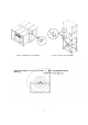
FIGURE 1: HORIZONTAL SPLIT ASSEMBLY FIGURE 2: VERTICAL SPLIT ASSEMBLY 8
Shipped Loose Intake or Discharge Dampers In some cases an intake or discharge damper may be shipped loose. This may be requested by the customer or can be required because of larger units shipping size restrictions. Follow these instructions to attach and wire the shipped loose damper. Factory mounted dampers may be attached on the unit and will not require assembly or field wiring. 1. Attach the damper to the intake or discharge using gasket, caulk, and #10 sheet metal screws 2.
14 x 14 30 222 77 x 28 66 12 16 x 16 36 225 88 x 32 75 15 20 x 20 45 227 96 x 36 81 18 24 x 24 54 230 104 x 38 90 20 26 x 26 60 233 116 x 44 99 22 30 x 30 66 236 122 x 44 108 25 32 x 32 75 27 36 x 36 81 WARNING!! 30 38 x 38 90 33 44 x 44 99 36 44 x 44 108 Failure to undersize ductwork size or length may cause system affect and reduce the performance of the equipment. Using the unit to support the ductwork may cause damage to the units casing.
Gas Gas piping must be installed to conform with local building codes, or in the absence of local codes, the National Fuel Gas Code, ANSI Z223.1 (NFPA 54) – latest edition. In Canada, gas piping must be installed in accordance with CAN/CGA-B149.1 for natural gas units and CAN/CGA-B149.2 for propane units. to or less than ½ PSI, the heater must be isolated from the gas supply piping system and its individual manual shutoff valve closed. 8.
Gas Connection Diagram Electrical Before connecting power to the heater, read and understand this entire section. Wiring diagrams are furnished with each fan by the factory, and are attached to the door of the unit. WARNING!! Disconnect power before installing or servicing fan. High voltage electrical input is needed for this equipment. This work should be performed by a qualified electrician. Electrical wiring must be done in accordance with local ordinances and the National Electric Code, ANSI/NFPA70.
9. If necessary, the original wire supplied with the heater may be replaced with type TW wire or the equivalent. Remote Control Panel For units with the remote control panel, a terminal strip inside the panel matches the terminals in the heater unit. Consult the as built wiring print supplied with the equipment. Most remote panels and VAV applications have signal wiring which needs to be shielded cable or in a separate conduit to avoid voltage interference.
modulating valve to maintain desired discharge temperature. Additional Sequence of Operation – All VFD Motor Control 1. During lower speeds, the low-speed potentiometer increases the resistance going to the modulating valve to limit temperature rise. 2. VFD contacts are included in the burner control circuit to disable the burner should a fault condition occur in the VFD.
Static Pressure Controller Installation Instructions Avoid locating the front of the static pressure controller in sun light or other areas with high ambient light or corrosive levels. Bright light shining on the photocells can cause false actuation of the load relays. The static pressure controller should be zeroed out before attaching the low and high pressure hoses. The zero adjustment is located between the minimum and maximum dials.
Check that all terminal screws are tight and that wires are in place Check pulley alignment. Correct if necessary Check that the power supply matches the nameplate voltage, phase, and amperage Record the voltage on the Start-Up Sheet Check that the gas type and pressure matches the nameplate type and pressure Check that the gas type and pressure matches the nameplate type and pressure Contact the service department is the power or gas supply needs to be changed in the field.
Turn the blower service switch or remote control device to ON. The (optional) intake or discharge damper motor will start to open. Once the damper is 90% open the damper motor internal end switch will close and energize the blower motor starter. Check that the motor amp draw is less than the FLA (full load amps) of the blower motor. The fan RPM may need to be reduced to decrease motor amps. Opening the driver (motor) pulley decreases RPM and motor amps.
PILOT REGULATOR Use the DC terminals on the flame safety to read the pilot flame signal POSITIVE TERMINAL NEGATIVE TERMINAL Record the pilot flame signal in the Start-Up Sheet Record the low and high fire flame signal on the Start-Up Sheet Setting High Fire Open the Burner Gas Shut Off Valve OPEN VALVE Measure the intake air temperature. Add the intake air temperature to the units nameplate design temperature rise. This result will be the desired high fire discharge temperature.
Use the Amplifier to override the heater into high fire. On discharge temperature control amplifier remove the #4 wire On the space temperature control amplifier remove the #2 and #4 wire On the M-Series adjust the set-point to be 160 F Adjust the manifold gas pressure to achieve the desired discharge air temperature. See the details for the high fire pressure adjustment locations.
Setting Low Fire Disconnect power to the amplifier or modulating valve Adjust the low fire setting on the modulation valve so the flame is full length of burner without dark spots See the details for the low fire pressure adjustment locations Use the burner observation port on the end of the unit to view the flame size Replace all amplifier wires in the place they were removed to set high and low fire Additional capacity is provided via a low fire bypass when MR212 low fire capacity is insufficient.
PROFILE ADJUSTMENTS The Direct-Fired Gas, make-up heater requires the correct air flow velocity across the burner. The air flow switch monitors the profile pressure differential, and will open the burner circuit if pressure difference is not within the allowed range. The air flow switches have low and high pressure settings for variable air volume units. The pressure drop should not be near the minimum and maximum of the air flow switch.
Variable Air Volume Profile VAV Profile VAV Profile In low speed, adjust the burner profile opening smaller to increase pressure drop or larger to lower pressure drop. In high speed adjust the bypass damper opening larger to decrease the pressure drop and smaller to increase the pressure drop.
Check Installation: √ Check The installation environment conforms to the VFD manual. The drive is mounted securely. Space around the drive meets the drive’s specification for cooling. The motor and driven equipment are ready for start. The drive is properly grounded. The input power voltage matches the drive’s nominal input voltage. The input power connections at U1, V2, and W1 are connected and tight. The input power protection is installed.
Signal Conditioner • • When computer of other process controls are specified, the signal conditioner provides compatibility with modulator / modulator-regulator valves. This system requires a field supplied 4 to 20 milliamp or 0 to 10 DC voltage signal. OTHER UNIT COMPONENTS Flame Safety Control The first system to understand is the Flame Safety Control. The FSC is Flame there only to monitor the flame, NOT to control temperature.
ELECTRICAL VESTIBULE 4 7 8 1 2 3 5 6 9 1 1 1 1 1 1. 2. 3. 4. 5. 6. 7. 8. 1 1 IGNITION TRANSFORMER INTAKE AIR THERMOSTAT FLAME SFAETY CONTROL MODULATING AMPLIFIER BLOWER SERVICE SWITCH BURNER SERVICE SWITCH CONTROL TRANSFORMER FREEZE CONTROL 9. 10. 11. 12. 13. 14. 15. 16. HIGH TEMPERATURE LIMIT POWER TRANSFORMER MOTOR STARTER MOTOT OVERLOAD CLOGGED FILTER SWITCH AIR FLOW PROVING SWITCH 120 VOLT TERMINALS 24 VOLT TERMINALS MANIFOLD VESTIBULE 8 7 6 5 3 2 4 1. 2. 3. 4.
TROUBLESHOOTING The following tables list causes and corrective actions for possible problems with direct fired heater units. Review these lists prior to consulting the manufacturer.
Burner Troubleshooting Chart Problem Pilot does not light/stay lit Potential Cause Main gas is off Air in gas line Dirt in pilot orifice Gas pressure out of range Pilot valve is off Leaking pilot orifice fitting Excessive drafts Safety device has cut power Dirty flame sensor Remote panel in “Vent” mode No spark at igniter Main burner does not light (Pilot is lit) Defective valve Loose valve wiring Defective pilot sensor Shut-off valve closed Defective flame safety controller Pilot fails as main gas valve
Remote Panel Troubleshooting Chart Light Indication No lights Condition Power not available to Remote Panel Proper heating operation Possible Cause Bad voltage to unit Main Disconnect in “OFF” position Circuit breaker tripped Bad main transformer No problem Manual/Off/Auto switch in “OFF” position (3-position Remote Panels only) Improper damper function Low Temperature Thermostat timed out (option) No problem Manual/Off/Auto switch in “OFF” position (2-position Remote Panels only) Heat/Vent switch in “VE
Troubleshooting Flowcharts Nothing Happens Is Overload tripped on starter? YES Reset & measure FLA of motor. Is it higher than rating? YES Adjust or change Pulley YES Is the air flow LED on Flame Saftey illuminated? Adjust or Replace Adjust pulley to achieve proper airflow.
Maxitrol Preliminary Circuit Analysis Series 14 System The basic Series 14 system consists of an amplifier, a discharge-air sensor and mixing tube, a remotetemperature selector, and a modulating valve or a modulator-regulator valve. Series 14 Preliminary Wiring Testing Procedures: • Disconnect the discharge-air sensor and replace with a 10,000-Ohm, 1/4-watt test resistor at Terminals 3 & 4. • Connect a dc-volt meter on the modulator-regulator or modulator-valve terminals.
Maxitrol Series 14 Troubleshooting Symptom No Gas Flow Continuous low fire (electronics problem) Continuous low fire (electronics OK) Incorrect minimum fire Possible Cause Modulating valve improperly installed Short circuit or no voltage to the amplifier Field Test Arrow on side of valve should point in direction of gas flow Check for 24-V at amplifier terminals 7 & 8 Remedy Install properly Open circuit in TD114 remote temperature selector or wiring Check wire connections between amplifier terminals
Symptom Continuous high fire (electronics OK) Possible Cause Foreign object holding valve open or plunger jammed Incorrect maximum fire Inlet pressure too low Erratic or pulsating flame Incorrect discharge air temperature Field Test Inspect: plunger should be smooth and clean, and operate freely in the solenoid valve. Read pressure at inlet to modulating valve using a manometer with unit operating at high fire.
Maxitrol Preliminary Circuit Analysis Series 44 System The basic Series 44 system consists of an amplifier, a discharge-air monitor with mixing tube, a selectrastat, and a modulating valve or a modulator-regulator valve. Series 44 Wiring for Preliminary Testing Procedures: • • • • • • • • Turn the test potentiometer to 2,000-Ohm minimum resistance. The dc voltage should read 0-V. Slowly turn the test potentiometer to maximum resistance or 12,000-Ohms.
Maxitrol Series 44 Troubleshooting Symptom No gas flow Continuous low fire (electronics problem) Continuous low fire (electronics OK) Incorrect minimum fire Possible Cause Modulating valve installed improperly No voltage to amplifier Field Test Arrow in side of valve should point in direction of gas flow.
Symptom Incorrect minimum or maximum discharge air temperature Possible Cause Improper TS144 location Field Test Compare sensed temperature at TS144 with average discharge air temperature Remedy Move TS144 to location where average temperature can be sensed Incorrect discharge air temperature control calibration Refer to the preliminary circuit analysis section Continuous high fire (electronics problem) Open in TS144 circuit Continuous high fire (electronics OK) Foreign material holding valve open
Flame Safety Service Guide (Airflow LED may or may not be illuminated) 36
Flame Safety Service Guide (continued) (Airflow LED may or may not be illuminated) 37
MAINTENANCE To guarantee trouble free operation of this heater, the manufacturer suggests following these guidelines. Most problems associated with fan failures are directly related to poor service and maintenance. WARNING!! DO NOT ATTEMPT MAINTENANCE ON THE HEATER UNTIL THE ELECTRICAL SUPPLY HAS BEEN COMPLETELY DISCONNECTED AND THE MAIN GAS SUPPLY VALVE HAS BEEN TURNED OFF. General Maintenance 1. Fan inlet and approaches to ventilator should be kept clean and free of any obstructions. 2.
2 Weeks after Start-Up 1. Belt tension should be checked after the first two weeks of fan operation. Belts tend to stretch and settle into pulleys after an initial start-up sequence. Do not tighten the belts by changing the setting of the motor pulley. This will change the fan speed and may damage the motor. To re-tension belts, turn disconnect OFF. Loosen the fasteners that hold the blower scroll plate to the blower. Rotate the motor to the left or right to adjust the belt tension.
START-UP CHECKLIST WARNING!! -The Start-Up must be completed after all field wiring and air balancing has been completed -The Start-Up must be completed by a qualified HVAC technician -The Start-Up Check list must be faxed into the Service Department to validate the product warranty JOB INFORMATION Job Name Address City State Zip Phone Number Fax Number Contact Purchase Date TECHNICIAN INFORMATION Service Company Address City State Zip Phone Number Fax Number Contact Start-Up Date Refer to the start-up p