
Manual


13
9. If necessary, the original wire supplied with the heater may be replaced with type TW wire or the
equivalent.
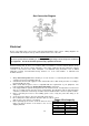
Remote Control Panel
For units with the remote control panel, a terminal strip inside the panel matches the terminals in the
heater unit. Consult the as built wiring print supplied with the equipment. Most remote panels and VAV
applications have signal wiring which needs to be shielded cable or in a separate conduit to avoid voltage
interference.
Power Supply Wiring
The units input power supply is listed on the unit nameplate. If the units power supply does not match the
unit nameplate contact the service department for a new wiring print and parts.
Paint Booth Applications
If a low temperature control is not an integral part of the heater, it is recommended that one be installed in
areas where freeze protection is needed in the event of a burner shutdown. The space should be
ventilated following a bake cycle to purge any contaminants and cool product prior to personnel entering
the space. If the unit was supplied with paint booth controls from the factory, refer to the schematic for
installation of the interlock to disable spraying equipment unless the heater is operating in ventilation
mode. Refer to electrical schematic for interlock to disable facility lighting within the process space during
the bake cycle.
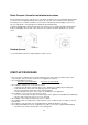
SEQUENCE OF OPERATIONS
Description of Operation
Designed for indoor or outdoor installation, the Direct Fired Gas Heater draws fresh outside air over a
gas-fired burner. The unit is equipped to fire with natural or propane gas. Units are designed for
modulated firing of the burner, based on the discharge-air temperature or room temperature requirement.
Standard Sequence of Operation
1. With disconnect in ON position and the remote control panel (or other device) calling for unit
operation, power is supplied to the damper motor, if equipped.
2. When the damper motor approaches the OPEN position, the damper-end switch closes, energizing
the motor contactor and powering the blower motor or enabling the VFD if equipped.
3. Power is supplied to the damper motor through the low-temperature limit control, if equipped. After
ten minutes, the low-temperature limit control disables the unit if discharge temperature is continually
below the temperature setting on the low limit control.
4. When the low airflow switch and high airflow switch (VFD only) are proven, the flame safety relay is
energized through the high-temperature limit control, the optional low and/or high gas pressure
switches, and the burner on/off intake air thermostat. The pilot valve opens, and the ignition
transformer energizes.
5. After the flame rod detects flame, the main valves are energized and the ignition transformer de-
energizes.
6. The temperature control system monitors the discharge air and modulates DC voltage to the