
Manual


9
Shipped Loose Intake or Discharge Dampers
In some cases an intake or discharge damper may be shipped loose. This may be requested by the
customer or can be required because of larger units shipping size restrictions. Follow these instructions to
attach and wire the shipped loose damper. Factory mounted dampers may be attached on the unit and
will not require assembly or field wiring.
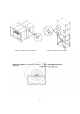
1. Attach the damper to the intake or discharge using gasket, caulk, and #10
sheet metal screws
2. Field wire the damper using the as built wiring schematic for the specific unit. Wiring may be different
depending on the model and options selected.
3. Refer to the factory supplied wiring print to verify the field wiring terminals.
Ductwork
This fan was specified for a specific CFM and static pressure. The ductwork attached to this unit will
significantly affect the airflow performance.
WARNING!!
• Flexible ductwork and square elbows should not be used
• Transitions and turns in ductwork near the fan outlet will cause system effect and will drastically
increase the static pressure and reduce airflow
• The Ductwork Sizing Chart shows the minimum fan outlet duct sizes and straight lengths
recommended for optimal fan performance
• Units with twin blower must have a common discharge plenum
Follow SMACNA guides and recommendations for the remaining duct run. Fans designed for
rooftop installation should be installed on a prefabricated or factory-built roof curb. Follow curb
manufacturer’s instructions for proper curb installation. It is recommended an outdoor unit be installed on
a curb and/or rail elevated so intake is not less than 20” above any surface. Be sure the duct connection
and fan outlet are properly aligned and sealed.
Adequate building relief is necessary in order to prevent over-pressurizing the building when the heater is
operating at capacity. This can be accomplished by establishing properly-sized relief openings, an
interlocked exhaust system, or both.
Heaters installed with intake ductwork must be purged to replace at least four air changes of the volume
of the intake duct.
In order to avoid hazards to other fuel-burning equipment in the building (i.e., when the heater is providing
make-up air to a boiler room), the unit should be interlocked to open inlet air dampers or other such
devices.
On outdoor installations, it is recommended that the discharge duct be insulated to prevent condensation
during the “OFF” cycle in cold weather.
Units being installed in airplane hangars should be installed in accordance with the Standard for Aircraft
Hangars, ANSI/NFPA 409. Units being installed in public garages should be installed in accordance
with the Standard for Parking Structures, ANSI/NFPA 88A, or the Standard for Repair Garages,
ANSI/NFPA 88B, and with CAN/CGA B149 Installation Codes.
Flexible connectors should be employed on all ductwork connections. Vibration isolators are optional and
can be supplied in the loose parts package.
Ductwork Sizing Chart Single Blower
Ductwork Sizing Chart Dual Blowers
Blower Size
Duct Size
(Inches)
Duct Length
(Inches)
Blower Size
Duct Size
(Inches)
Duct Length
(Inches)