Modular In-Direct Fired Heaters and Inserts Installation, Operation, and Maintenance Manual Modular In-Direct Fired Heater In-Direct Fired Module FOR YOUR SAFETY If you smell gas: 1. Open windows. 2. Don’t touch electrical switches. 3. Extinguish any open flames. 4. Immediately call your gas supplier. In-Direct Fired Furnace FOR YOUR SAFETY The use and storage of gasoline or other flammable vapors and liquids in open containers in the vicinity of this appliance is hazardous.
TABLE OF CONTENTS WARRANTY ............................................................................................................................................ 3 INSTALLATION ....................................................................................................................................... 4 Mechanical .......................................................................................................................................... 4 Site Preparation ......................
WARRANTY This equipment is warranted to be free from defects in materials and workmanship, under normal use and service, for a period of 12 months from date of shipment. This warranty shall not apply if: 1. The equipment is not installed by a qualified installer per the MANUFACTURER’S installation instructions shipped with the product, 2. The equipment is not installed in accordance with federal, state and local codes and regulations, 3. The equipment is misused or neglected, 4.
INSTALLATION It is imperative that this unit is installed and operated with the designed airflow, gas, and electrical supply in accordance with this manual. If there are any questions about any items, please call the service department at 1-866-784-6900 for warranty and technical support issues. Mechanical WARNING: DO NOT RAISE VENTILATOR BY THE INTAKE HOOD, BLOWER OR MOTOR SHAFT, OR BEARINGS – USE LIFTING LUGS PROVIDED OR A SLING Site Preparation 1.
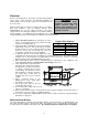
Recommended Supply Ductwork Sizes drastically increase the static pressure and reduce airflow. The chart below shows the Blower Size Straight Duct Length minimum fan outlet duct sizes and straight 10 48 in. lengths recommended for optimal fan 15 72 in. performance. Follow SMACNA guides and 18 86 in. recommendations for the remaining duct run. Fans designed for rooftop installation should be installed on a prefabricated or factory built roof curb.
In-Direct Fired Module Installation Indoor (INLINE) Installation 6
Indoor Flue Venting Indoor gas fired heating equipment must be vented. Do not operate un-vented. Gas fired heating equipment which has been improperly vented, or which experiences a blocked vent condition may emit flue gases into heated spaces. 1. Installation of venting must conform with local building codes, or in the absence of local codes, with the National Fuel Gas Code. 2. Do not use a vent pipe smaller than the size of the outlet on the heater. 3. Reference Table 2.1.
Gas Installation of gas piping must conform with local building codes, or in the absence of local codes, with the National Fuel Gas Code, ANSI Z223.1 (NFPA 54) – latest edition. In Canada, installation must be in accordance with CAN/CGA-B149.1 for natural gas units and CAN/CGA-B149.2 for propane units. WARNING: INLET GAS PRESSURE MUST NOT EXCEED 14 IN. W.C. SEE UNIT RATING PLATE FOR PROPER GAS SUPPLY PRESSURE AND GAS TYPE. 1. Always disconnect power before working on or near a heater.
Electrical Before connecting power to the heater, read and understand this entire section of this document. As-built wiring diagrams are furnished with each fan by the factory, and are attached to the door of the unit. WARNING!! Disconnect power before installing or servicing fan. High voltage electrical input is needed for this equipment. This work should be performed by a qualified electrician.
Remote Control Panel On units shipped with the optional remote control panel, an electrical drop containing the panel wiring is provided with the heater. There is a terminal strip inside the remote panel that matches the terminals in the heater unit. The remote panel should be wired as shown below.
OPERATION Prior to starting up or operating the heater, check all fasteners for tightness. In particular, check the set screw in the wheel hub, bearings and the fan sheaves (pulleys). With power and gas to the heater OFF or prior to connecting ventilator to power, turn the fan wheel by hand to be sure it is not striking the inlet or any obstacles. Re-center if necessary.
Main Burner Adjustment 1. Once the pilot has been properly established, the manifold gas pressure should be adjusted to jobsite conditions. The gas pressure regulator (integral to the combination gas control) is adjusted at the factory for average gas conditions. It is important that the gas be supplied to the furnace in accordance with the input rating on the rating plate. 2. Create a high fire call for heat. This should be Maxitrol Modulating Valve done with the blower on and all gas controls on.
Furnace Start Up Summary Is incoming gas pressure 7"-14"?(11"-14" for LP) No Adjust incoming gas pressure. Yes Adjust pilot flame. Setting incoming pressure: Presure must be measured at first "T" in supply gas line before the first gas valve. Adjusting the pilot: The pilot flame should be 3/4" to 1" long and encompass 3/8" to 1/2" of the tip of the flame sensing rod. Lock unit into high fire. Is there 3.5" w.c. (10" w.c. propane) max.
Final Start Up Procedure 1. With the air and burner systems in full operation and all ducts attached, measure the system airflow. Motor sheave (pulley) is variable pitch, and allows for an increase or decrease of the fan RPM to adjust the airflow, as shown in the illustration below. For your convenience, a RPM chart is included in the following pages. 2. Once the proper airflow is achieved, measure and record the fan speed with a reliable tachometer.
Pulley Adjustment Pulley Setscrew Torque The adjustable motor pulley is factory set for the RPM specified. Speed can be increased by closing or decreased by opening the adjustable motor sheave. Two groove variable pitch pulleys must be adjusted an equal number of turns open or closed. Any increase in speed represents a substantial increase in horsepower required by the unit. Motor amperage should always be checked to avoid serious damage to the motor when the speed is varied.
Pulley Combination Chart Motor RPM 1725 1/3 to 1-1/2 HP MOTOR PULLEY AX BELTS 1VL34 Dd1 Dd2 Pd1 1.9 2.9 2 Pd2 3 Open BLOWER PULLEY AK114 TURNS ON MOTOR PULLEY PITCH DIAMETER 5 4 1/2 4 3 1/2 3 2 1/2 2 1 1/2 1 1/2 0 11 11.2 308 323 339 354 370 385 400 416 431 447 462 Dd1 Dd2 Pd1 Pd2 2.4 3.4 2.6 3.
Flame Safety Control The second system to understand is the Flame Safety Control. The FSC is Flame Safety there only to monitor the flame, NOT to control temperature. The FSC uses a sensor mounted on the burner pilot assembly to sense for pilot establishment. The FSC controls the opening of the redundant solenoid gas valves and the operation of the spark igniter to initiate a pilot flame upon start up.
Optional Remote Panel Circuit Power Supply From Heater "Power" Light Off No Power to Panel On Panel is Powered Blower Switch "Blower Off" Position (3-Position Panels Only) Nothing Happens No Power is Sent to Heater "Blower On" Position Power is Sent to Heater to Open Damper (if provided) and Start Blower "Blower On" Light Off Damper is not Open or FreezeStat has Detected Low Temperature Operation On Blower Operates Cooling Circuit is Energized "Cool" Position (if provided) Blower Operates Te
Components The following image and list outlines the typical in-direct fired heater components and their functions. 1. Power Transformer – Installed when motor voltage > 120V. Used 1 to provide 120V service to controls. 17 8 2. Control Transformer – 120V primary; 24V secondary control transformer. 2 3. Discharge Temperature Set-Point 7 18 9 13 – Controls the discharge air temperature. Furnace will not light if air temperature is higher than set10 3 point. 19 22 16 4.
Remote Panel Option The Remote Panel is a device used to control the operation of the heater from a remote location. This unit is available in both a “2 Position” or “3 Position” configuration and with or without a cooling output. It also will accommodate both the Maxitrol discharge temperature dial and the Maxitrol space sensing Selectrastat. It is important to understand the following Remote Panel controls and uses: 3 1 4 2 HEAT ON LOW TEMP CLOGG ED 1.
Troubleshooting The following tables list causes and corrective actions for possible problems with in-direct heater units. Review these lists prior to consulting manufacturer.
Furnace Troubleshooting Chart Problem Pilot Does Not Light/Stay Lit Potential Cause Main gas if off Air in gas line Dirt in pilot orifice Gas pressure out of range Pilot valve is off Pilot orifice fitting leak Excessive drafts Safety device has cut power Dirty flame sensor Remote panel in “Vent” mode No spark at igniter Main Burners Do Not Light (Pilot is Lit) Defective valve Loose valve wiring Defective pilot sensor Shut off valve closed Defective ignition controller Unit cycling on high limit Not Enou
Remote Panel Troubleshooting Chart Light Indication No Lights Condition Power not available to Remote Panel POWER Light Only Proper unit Off Operation No power to motor starter Improper Airflow POWER Light and BLOWER ON Light Proper Ventilation Operation No Power to Flame Safety Controller CLOGGED FILTER Light On (Optional) LOW TEMP Light On (Optional) POWER Light and BLOWER ON Light and HEAT ON Light Filters Clogged Freeze-stat has shut blower down Proper Heating Operation 23 Possible Cause Bad v
Troubleshooting Flowcharts Nothing Happens Is Overload tripped on starter? YES Reset & measure FLA of motor.
MAINTENANCE To guarantee trouble free operation of this heater, the manufacturer suggests following these guidelines. Most problems associated with fan failures are directly related to poor service and maintenance. Please record any maintenance or service performed on this fan in the documentation section located at the end of this manual. WARNING: DO NOT ATTEMPT MAINTENANCE ON THE HEATER UNTIL THE ELECTRICAL SUPPLY HAS BEEN COMPLETELY DISCONNECTED AND THE MAIN GAS SUPPLY VALVE HAS BEEN TURNED OFF.
2 weeks after startup 1. Belt tension should be checked after the first 2 weeks of fan operation. Belts tend to stretch and settle into pulleys after an initial start-up sequence. Do not tension belts by changing the setting of the motor pulley, this will change the fan speed and may damage the motor. To retension belts, turn the power to the fan motor OFF. Loosen the fasteners that hold the blower scroll plate to the blower. Rotate the motor to the left or right to adjust the belt tension.
Orifice and Gas Consumption Chart Furnace Size 200 350 400 No. of Orifices 3 6 6 Natural Gas Orifice Drill Size 23 27 23 Propane Gas Orifice Drill Size 40 43 40 27 Natural Gas CFH 192.3 336.5 384.
Start-Up and Maintenance Documentation START-UP AND MEASUREMENTS SHOULD BE PERFORMED AFTER THE SYSTEM HAS BEEN AIR BALANCED AND WITH THE HEAT ON (Warranty will be void without completion of this form) Job Information Job Name Address City State Zip Phone Number Fax Number Contact Purchase Date Service Company Address City State Zip Phone Number Fax Number Contact Start-Up Date Heater Information Refer to the start-up procedure in this manual to complete this section.