Non-Welded Grease Duct Systems Installation, Operation, and Maintenance Manual FOR YOUR SAFETY TWO MAJOR CAUSES OF GREASE DUCT RELATED FIRES: (1) FAILURE TO MAINTAIN REQUIRED CLEARANCE (AIR SPACE) TO COMBUSTIBLE MATERIALS AND (2) FAILURE TO CLEAN GREASE LADEN DUCTS. IT IS OF UTMOST IMPORTANCE THAT THIS GREASE DUCT BE INSTALLED ONLY IN ACCORDANCE WITH THESE INSTRUCTIONS. DO NOT INSTALL GREASE DUCT WITHOUT FIRST READING THESE INSTRUCTIONS VERY CAREFULLY.
TABLE OF CONTENTS WARRANTY ............................................................................................................................................ 3 LISTINGS ................................................................................................................................................ 4 APPLICATION......................................................................................................................................... 4 MECHANICAL ........................
WARRANTY This duct work system is warranted to be free from defects in material and workmanship, under normal use and service, for a period of 12 months from the date of shipment. This warranty shall not apply if: 1. The equipment is not installed by a qualified installer per this installation guide, this guide should be kept with the equipment once installation is complete. 2. The equipment is not installed in accordance with federal, state and local codes and regulations. 3.
LISTINGS This grease duct is ETL listed to standard UL-1978 when installed in accordance with these installation instructions and National Fire Protection Association Standard “NFPA 96, Standard for Ventilation Control and Fire Protection of Commercial Cooking Operations”. APPLICATION The listed grease duct is suitable for use in commercial cooking installations for the removal of smoke and grease laden vapors.
MECHANICAL Joint Sealant The joint sealant used to seal all joint assemblies is a 3M product. 3M Fire Barrier 2000 + Silicone Sealant is a ready-to-use, gun-grade, one-component silicone elastomer that cures upon exposure to atmospheric humidity to form a flexible seal. 3M Fire Barrier 2000 + Silicone Sealant, when installed properly, will control the spread of fire before, during and after exposure to open flames.
Grease Duct Standard Connection 1. Apply a continuous bead of proper sealant around the flange to be joined. The bead should be ¼” thick and continuous. 2. Join the two flanged ends of the duct section together. 3. Fill the “V” clamp with the proper sealant. The bead should be inside the “V”. 4. Install the “V” clamp around the duct sections. Both duct flanges should be inside the “V”. 5.
Collar & Adjustable Duct Connections The collar and the adjustable length duct have two major functions: (1) Make up odd lengths of duct as needed in short runs as in termination of the duct at the exhaust fan. (2) Serve as an expansion joint for thermal expansion in larger runs of duct. When used in systems of any orientation, it can perform both functions simultaneously.
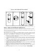
Fig. 2b – Collar & Adjustable Duct Installation Risers – Factory & Field (Bolted & Welded) Risers There are two options for the riser (connection to hood plenum); Factory welded and field welded or bolted. Dimensional data identifying the size and location of the riser must be provided for factory installation. The riser is fully welded to the hood plenum. When field installed, the riser is shipped loose allowing the installer at the jobsite to decide on the final location of the riser.
Fig. 3 – Field Installed Riser - Bolted S ta n d a rd d u c t "V " c la m p R is e r w ith re ta in in g rin g R e ta in in g rin g T op of hood 1 /4 -2 0 H a rd w a re Duct Drains Drains are used to provide a point at which low points in the duct system can be drained. Condensation and low lying water left over from duct cleaning can be drained easily with the installation of the ball valve drain.
Access Door (Tee Cap) Assembly Access doors (tee caps) are available 8” to 24”. They work in conjunction with the manifold tee as previously shown in Fig. 5. The tee joint connection is shown in Fig. 1 – JOINT ASSEMBLY; however, the installation of the access door is slightly different so read the following instructions very carefully. Consult NFPA 96, Chapter 7, Section 7.3.1 “Openings shall be provided at the sides or at the top of the duct, whichever is more accessible, and at change of directions”. 1.
Fan Adapter Plate The fan adapter plate (Transition Plate) is designed to connect to a roof curb. The duct section is welded to the underside of the adapter plate. The adapter plate is formed to provide a slope to allow grease deposits to flow back towards the duct. When connected, see Fig. 7, the plate mounts on top of the fan curb, which supports the fan housing. The plate may be positioned off center within the curb provided that the minimum distance to combustibles is maintained.
Fig. 8 – Horizontal Support Details IMPORTANT: VERTICAL & HORIZONTAL SUPPORTS SHOWN IN THIS MANUAL ARE RECOMMENDED. SUPPORTS BY OTHERS MUST BE APPROVED BY THE MANUFACTURER AND AHJ. SUPPORT SPACING MUST BE AS STATED IN THIS MANUAL. Wall Guide Support & Support Vertical Spacing OD + 4" See table 3 3/8" Threaded Rod Duct Angle / Unistrut Duct Wrap Inner Layer Duct Wrap Outer Layer 6" Collar The wall guide is to be attached to Non-Combustible and Combustible surfaces.
Fig. 9 – Vertical Support Details IMPORTANT: VERTICAL & HORIZONTAL SUPPORTS SHOWN IN THIS MANUAL ARE RECOMMENDED. SUPPORTS BY OTHERS MUST BE APPROVED BY THE MANUFACTURER AND AHJ. SUPPORT SPACING MUST BE AS STATED IN THIS MANUAL.
Grease Duct Assembly Examples Grease Duct Installation: Fig. 10 - Grease Duct Installation Guide The illustration shown provides useful information on the installation of grease duct systems. Each installation is specific to the application and the job site. When duct systems are installed outside, welded seams must be painted with corrosion resistant high temperature paint. If you encounter a situation not covered by this illustration, refer to the guide or consult the factory.
Fig. 11 - Grease Duct Installation Guide Adjustable ducts and standard ducts can be used to terminate at the transition plate. The duct is fully welded to the transition plate ate the factory. Grease Duct Installation: The illustration shown provides useful information on the installation of grease duct systems. Each installation is specific to the application and the job site. When duct systems are installed outside, welded seams must be painted with corrosion resistant high temperature paint.
Fig. 12 - Grease Duct Installation Guide Grease Duct Installation: The illustration shown provides useful information on the installation of grease duct systems. Each installation is specific to the application and the job site. When duct systems are installed outside, welded seams must be painted with corrosion resistant high temperature paint. If you encounter a situation not covered by this illustration, refer to the guide or consult the factory.
CLEARANCES This grease duct is primarily intended for use in non-combustible surroundings, when installed in a room where enclosure is not required. Grease duct may be located at clearance to combustibles in accordance with Table 5. Grease duct may be located in a corner formed by two combustible walls provided the minimum clearance is maintained.
Zero Clearances to Combustibles This duct is to be used in non-combustible surroundings. Where the duct does not require an enclosure, it must have a minimum clearance to adjacent combustible walls as shown above in Table 5 – CLEARANCES. In cases where the ducting extends through any story of a building above the location at the connected appliances, it must be enclosed in the upper stories with walls having a fire resistance rating of not less than one hour for buildings of two or three stories in height.
NOTES ______________________________________________________________________________ ______________________________________________________________________________ ______________________________________________________________________________ ______________________________________________________________________________ ______________________________________________________________________________ ______________________________________________________________________________ ________________________________
CLEANING & MAINTENANCE RECORD Date Service Performed Factory Service Department Phone: 1-866-784-6900 Fax: 1-919-554-2415 20