
Manual

1.
Make sure that the power is disconnected from the fan.
2. Remove fan hood by releasing the hood retaining clips.
3. Disconnect the motor wire harness by unsnapping the quick release
connection.
4. Remove all ¼-20 nylon inserted nuts and nylon washers from the
baffle, see detail A.
5. Remove all of the ¼-20 x 1” sheet metal screws that secure the apron
to the baffle.
6. Loosen all the ¼-20 pan head bolt located under the horizontal brace,
see detail A.
7. The vertical brace should now be loose. Push the vertical brace studs
into the baffle using a screw driver. Follow this method until all the
studs have been pushed into the baffle area, see detail A.
8. You will be able to remove the main assembly from the baffle by
pulling up on the apron, see main assembly view.
9. You must remove the wheel before gaining access to the hardware
that holds the motor in place.
10. Loosen the hardware that holds the wheel in place. Loosen the nuts
and then the set screws. Lock tight has been used to help secure this
hardware so they might be tight.
11. The motor shaft has been designed with two flat areas. This allows
the set screws to secure the motor, and also prevent the motor shaft
from getting stuck during removal from the fan.
12. Now that the wheel has been removed you will be able to remove the
hardware that holds the motor in place.
13.
When mounting the new motor it is very important to attach the 10/32
nuts to the face of the motor
, this creates a gap between the surface of
the motor plate and the face of the motor.
14. Mount the motor, align motor studs with motor plate mounting hole
and secure with 10/32 nuts on the under side of motor mounting plate
.
15. Reattach the wheel, the face of the hub should be flush with the end
of the shaft. Make sure that the set screws are over the flats on the
motor shaft and lock tight is used before tightening the set screws.
Remember to tighten the nuts as this will stop the set screws from
backing out.
16. Make sure that the wheel spins freely and is centered over the inlet.
17. Insert the main assembly back in to the baffle making sure to align
the vertical braces studs with the mounting holes. Reach inside the
unit and pull the vertical brace studs through the baffle holes, secure
with nylon washers and ¼-
20 nylon inserted nuts. Follow this method
until all vertical braces are secure, see detail A.
18. Tighten all the ¼-20 pan head bolt located under th
e horizontal brace,
see detail A.
19. Reuse all of the ¼-20 x 1” sheet metal screws that secure the apron to
the baffle.
20. Make sure that the wheel spins freely and is centered over the inlet.
21. Reconnect the motor wire harness by snapping the quick release
connections together.
22. Fan hood should be put on the unit, make sure the hood retaining
clips are snapped shut.
23. Reconnect the power and test run unit.
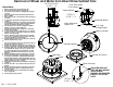
Top Plate.
Motor.
B
Instructions:
Removal of Wheel and Motor from Direct Drive Upblast Fans
Rev. 1 09/21/2004
AA
AA
SECTION AA-AA
SCALE 1 : 18
A
Vertical Brace.
Nylon Washer &
Only Loosen.
Through Baffle.
SCALE 1 : 12
Push Stud
DETAIL A
Nylock Nut.
1/4-20 Pan Head
Horizontal Brace.
Base Assembly.
DETAIL B
SCALE 1 : 4
ISOLATORS ARE NOT
USED ON WALL MOUNT
APPLICATIONS.
MOTORS ARE MOUNTED
DIRECTLY TO THE TOP
PLATE.
Vertical Support.
Main Assembly.
Wheel Set Screws.
1.
Make sure that the power is disconnected from the fan.
2. Remove fan hood by releasing the hood retaining clips.
3. Disconnect the motor wire harness by unsnapping the quick release
connection.
4. Remove all ¼-20 nylon inserted nuts and nylon washers from the
baffle, see detail A.
5. Remove all of the ¼-20 x 1” sheet metal screws that secure the apron
to the baffle.
6. Loosen all the ¼-20 pan head bolt located under the horizontal brace,
see detail A.
7. The vertical brace should now be loose. Push the vertical brace studs
into the baffle using a screw driver. Follow this method until all the
studs have been pushed into the baffle area, see detail A.
8. You will be able to remove the main assembly from the baffle by
pulling up on the apron, see main assembly view.
9. You must remove the wheel before gaining access to the hardware
that holds the motor in place.
10. Loosen the hardware that holds the wheel in place. Loosen the nuts
and then the set screws. Lock tight has been used to help secure this
hardware so they might be tight.
11. The motor shaft has been designed with two flat areas. This allows
the set screws to secure the motor, and also prevent the motor shaft
from getting stuck during removal from the fan.
12. Now that the wheel has been removed you will be able to remove the
hardware that holds the motor in place.
13.
When mounting the new motor it is very important to attach the 10/32
nuts to the face of the motor
, this creates a gap between the surface of
the motor plate and the face of the motor.
14. Mount the motor, align motor studs with motor plate mounting hole
and secure with 10/32 nuts on the under side of motor mounting plate
.
15. Reattach the wheel, the face of the hub should be flush with the end
of the shaft. Make sure that the set screws are over the flats on the
motor shaft and lock tight is used before tightening the set screws.
Remember to tighten the nuts as this will stop the set screws from
backing out.
16. Make sure that the wheel spins freely and is centered over the inlet.
17. Insert the main assembly back in to the baffle making sure to align
the vertical braces studs with the mounting holes. Reach inside the
unit and pull the vertical brace studs through the baffle holes, secure
with nylon washers and ¼-
20 nylon inserted nuts. Follow this method
until all vertical braces are secure, see detail A.
18. Tighten all the ¼-20 pan head bolt located under th
e horizontal brace,
see detail A.
19. Reuse all of the ¼-20 x 1” sheet metal screws that secure the apron to
the baffle.
20. Make sure that the wheel spins freely and is centered over the inlet.
21. Reconnect the motor wire harness by snapping the quick release
connections together.
22. Fan hood should be put on the unit, make sure the hood retaining
clips are snapped shut.
23. Reconnect the power and test run unit.