FloorHeat PRE-ASSEMBLED RADIANT CONTROL PANEL INSTALLATION MANUAL
Thank you for purchasing this radiant control panel assembly. Following are some important notes that will make the installation successful. • Read through the entire manual before starting installation • Do NOT plug in the power cord until the panel is installed, connected, and the fluid has been filled. • If there has been damage in shipment, please call 888-265-5455 for troubleshooting, returns, and replacement parts. Do NOT return the panel to the store.
INSTALLATION 1. Planning the installation. The control panel should be mounted on a wall or permanent vertical surface near the boiler for convenient plumbing and wiring. It should be mounted at a convenient height to ease installation and maintenance. 2. Panel Mounting. Once the location has been determined, drill (2) ¼" diameter holes on each of the four panel mounting flanges. Install a 1x wood cleat, 28" long, to the mounting surface where the top panel flange will be mounted.
. Manifold transmission lines. Using ¾" type L copper tubing or ¾" oxygen barrier PEX tubing, route the transmission lines from the control panel to the zone manifold(s). Referring to the appropriate panel schematic in the appendix, note the location of the supply and return lines. Customarily, the upper zone manifold is the return to bring any trapped air back to the control for purging.
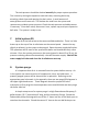
The tank pressure should be checked annually for proper system operation. This is done by closing the expansion tank ball valve, removing drain cap, attaching a drain hose and opening the drain valve. A small amount of water/pressure will come out. This isolates the tank from the system and removes any residual system pressure. Check the tank pressure and add pressure if necessary. Close drain valve, disconnect hose, replace cap, and open expansion ball valve. The system is ready to use. 7.
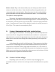
noted on the schematic. This second hose returns to the 5-gallon bucket. With the pump in the bucket, fill the bucket with clean water. Each of the ball drain valves have two ball valves. The ball valve where the hose attaches, simply opens and closes the line. The second ball is actually a 3way valve, which can direct water flow straight through or one direction or the other. The ball valve handle decal indicates flow direction.
boiler is closed. Plug in the submersible pump and slowly open both inlet ball valves on the ball drain valves. Water should now flow through the boiler and return water and air to the bucket. When the return line is free of air bubbles, quickly close both inlet ball valves on the ball drain valves. Turn off the pump. The system is now purged of air. Disconnect the purge line and replace the drain valves caps. Position the drain valves 3-way ball valves to the flow through position.
11. System start up. With the boiler power shut off, activate all of the thermostats. All of the zone circulators should turn on. There may be an initial gurgling noise, but as any remaining air is vented out the air eliminator, the system should be quiet in a couple minutes. Check for leaks. Turn boiler power on. The boiler circulator should turn on and the boiler fire up. Observe temperature and pressure gauges.
Appendix 1-4 Zone Control Panel for Condensing Boiler
5-8 Zone Control Panel for Condensing Boiler
1-4 Zone Control Panel for Non-Condensing Boiler
5-8 Zone Control Panel for Non-Condensing Boiler